This is a comprehensive guide on getting started with Raspberry Pi Pico & Pico W using MicroPython. This detailed guide will provide step-by-step instructions to connect and upload code to Pico. At the end of this Raspberry Pi Pico tutorial, you shall learn how to blink the onboard LED in Raspberry Pi Pico using MicroPython. Pi Pico can also be programmed using C/C++.
This tutorial is written for Windows OS and will demonstrate the process of uploading MicroPython code using two IDEs:
- Thonny IDE.
- uPyCraft IDE.
Here are some other getting-started guides for Raspberry Pi Pico that you might find helpful:
- Our tutorial to Program Raspberry Pi Pico using Arduino IDE will help you to use Arduino code for Pico.
- If you are using macOS, visit our article How To Program Raspberry Pi Pico On macOS Using Thonny IDE.
Raspberry Pi Pico Specifications
Raspberry Pi Pico is a development board based on the RP2040 microcontroller, a dual-core Arm Cortex M0+ processor. It has 264kB on-chip SRAM in six independent banks and 2MB of flash memory. The flash memory can be extended using a dedicated QSPI bus.
It also features an onboard temperature sensor, not seen in other boards in this segment. To know more on how to read the onboard temperature sensor, you can visit our article Raspberry Pi Pico Onboard Temperature Sensor Tutorial Using MicroPython.
The connectivity front includes two SPI controllers, two I2C controllers, two UARTs, and USB1.1. The board features 3 12-bit ADCs for high-resolution analog to digital conversions.
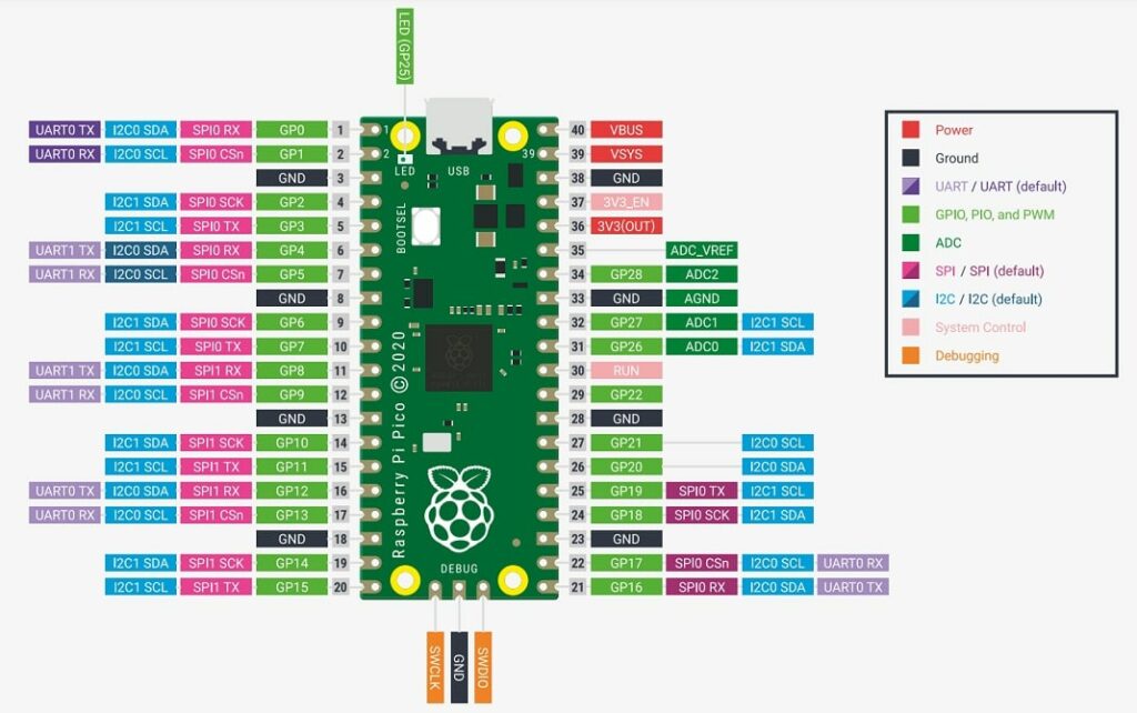
There are 30 GPIO pins. Out of these, 26 are available to use through the pin-headers. The pinout of both Raspberry Pi Pico & Pico W is similar in most aspects. You can learn more about the pinouts in our in-depth article: A Guide to Raspberry Pi Pico & Pico W Pinout- All Pins Explained.
The pins GP23, GP24, GP25, and GP29 are not available in the board’s pinout. They are used for specific functions as shown in the table below.
| PIN | DESCRIPTION |
| GPIO 23 | Used to control the on-board SMPS Power Save pin |
| GPIO 24 | VBUS sense – HIGH if VBUS is present, else LOW |
| GPIO 25 | Connected to the on-board LED |
| GPIO 29 | Used in ADC mode (ADC3) to measure VSYS/3 |
Note that, unlike many Arduino boards, Pico pins operate at 3.3V. So if you have any input peripherals that output 5v, be sure to use an appropriate logic level converter. Pico has a flexible clock that can run up to 133 MHz. You can access the Pi Pico datasheet here.
Here is the pinout of Raspberry Pi Pico / Raspberry Pi Pico H:
Raspberry Pi Pico W Specifications
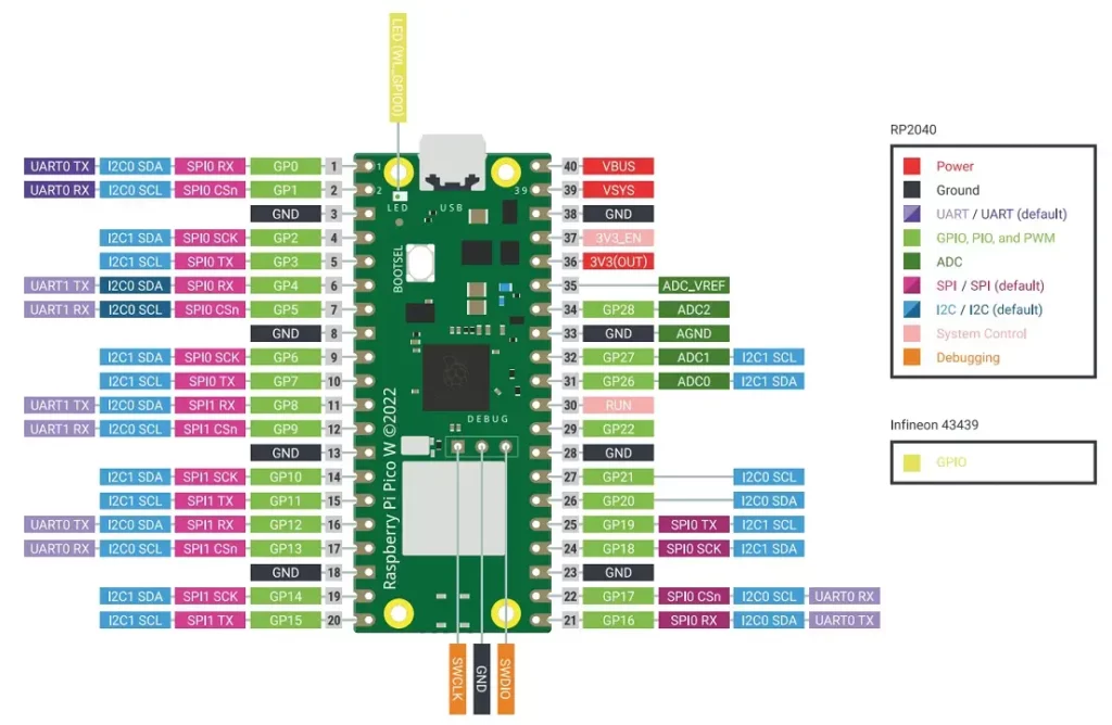
Most features of the Raspberry Pi Pico W version are similar to the first Raspberry Pi Pico variant. The Raspberry Pi Pico W maintains the Pico small factor while adding on-board single-band 2.4GHz wireless ports (802.11n), utilizing the Infineon CYW4343 chip. Infineon CYW4343 features a single-band 2.4 GHz Wi-Fi 4 (802.11n) and Bluetooth® 5.1. The RP2040 microprocessor is connected to the wireless interface via SPI.
Like the Pi Pico original version, 26 out of 30 GPIOs are available through the pin headers. GP23, GP24, GP25, and GP29 retain the same functionality described in Table 1 above. Three GPIO pins from the Infineon CYW43439 are used for some specific functions:
| Pin Name | Function |
| WL_GPIO0 | Connected to onboard LED. |
| WL_GPIO1 | Controls the on-board SMPS power save pin. |
| WL_GPIO2 | Senses the VBUS voltage. It is in a HIGH state if VBUS is present, else its state is LOW. |
Below is the pinout of Raspberry Pi Pico W and Raspberry Pi Pico WH.
How to Power Raspberry Pi Pico
A micro USB cable is used to power Raspberry Pi Pico and upload code to it. The VBUS pin (Pin 40) is connected to the micro-USB port pin 1, so it stays at around 5V when connected to a computer. The voltage at VBUS is fed through a Schottky diode onboard to generate VSYS voltage.
VSYS (Pin 39) is the primary input voltage for Pico, which can be in the range of 1.8V to 5.5V.
Read our comprehensive guide on powering Raspberry Pi Pico with batteries shows examples of powering Pico with 9V, 12V AA, or AAA batteries.

Soldering Pin Headers
Four variants of Raspberry Pi Pico are available while publishing this article:
- Raspberry Pi Pico 2020 (First variant).
- Raspberry Pi Pico H.
- Raspberry Pi Pico W.
- Raspberry Pi Pico WH.
The ‘H’ stands for “Headers” and these two boards has pin headers pre-soldered.
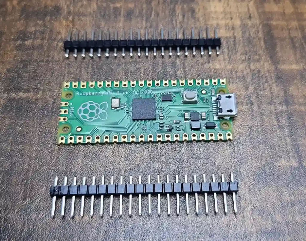
Pico comes with castellated mounting points and plated holes on the non-header variants. Soldering pin headers (Berg strips) to the holes will make it easier to prototype projects using a beadboard. Pico has 40 pins, 20 on each side. Cut your pin headers in groups of 20 like the image below.
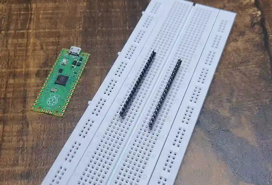
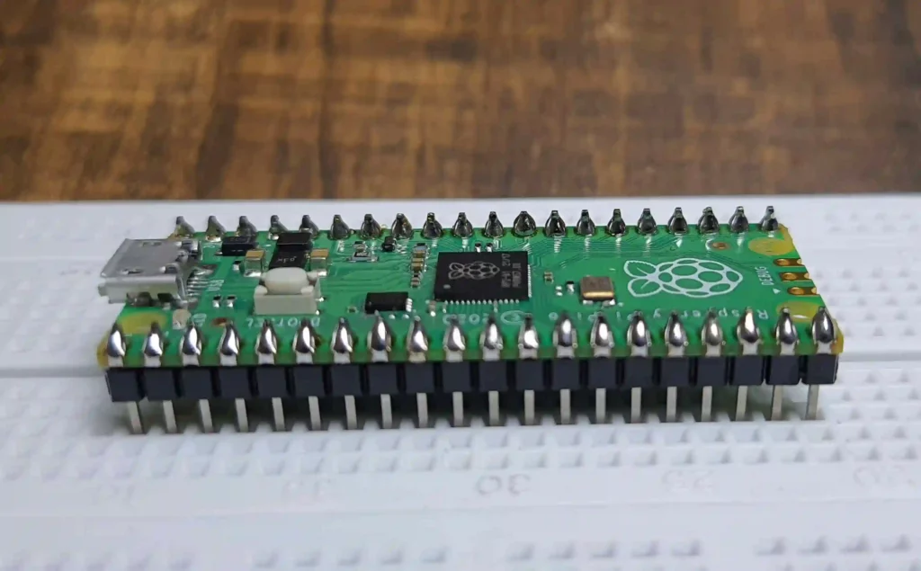
For easier soldering, insert the pin headers into the breadboard as shown in the following image. Place your Pico atop the pins and solder the header pins to the holes in Pico. Make sure that the connections are proper.
Soldering Tips:
- Apply flux to the soldering points.
- Heat your soldering iron to around 650/670 °F.
- Apply a little solder to your soldering iron to aid in the proper transfer of heat.
- Then heat the pins with the soldering iron and apply solder to the heated pins, one by one.
What is MicroPython?
MicroPython is a port of Python 3 that is specifically designed to work with low-power microcontrollers. It features a subset of the standard Python library and is optimized to run on bare metal processors. Although MicroPython is not a full implementation of Python, its syntax and features are the same to an extent.
So, if you are experienced with Python, then you can easily get started with MicroPython. MicroPython has a built-in filesystem and allows us to execute commands via USB Serial. We get an interactive prompt called the REPL to interact with the microcontroller.
The REPL in MicroPython
When we power up the Raspberry Pi Pico, it waits for user commands to perform an action. The fastest way to interact with it is through REPL. REPL stands for read-evaluate-print loop.
In the read phase, MicroPython waits for code to be written on the shell of an IDE. Upon pressing the “Enter” key, Micropython evaluates the code that was typed and runs it immediately. If any result is to be shown, it is printed for the user to view. This process continues in a loop, i.e. it again goes back to the read phase and waits for the next line of code to be written.
The REPL environment is very fast and shows results immediately. On the contrary, C/C++ code is compiled first, so development in MicroPython can be faster than in C/C++.
Steps to Run MicroPython Code on Raspberry Pi Pico
- Flash MicroPython firmware on Raspberry Pi Pico.
- Install a MicroPython IDE (Integrated Development Environment).
- Write a MicroPython script in the IDE and upload it to RPi Pico using a USB cable.
How to Flash MicroPython Firmware on Raspberry Pi Pico
1. Download the MicroPython UF2 file for the Raspberry Pi Pico or Raspberry Pi Pico W. UF2 is a file format that is suitable for flashing microcontrollers over USB.
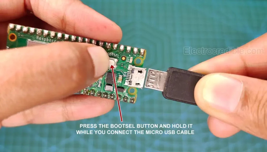
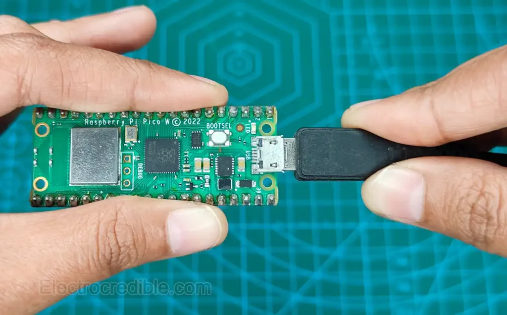
2. Press and hold the BOOTSEL button on Pico and connect a micro USB cable. The other end of the USB cable should be connected to your computer. After proper connection, release the BOOTSEL button.
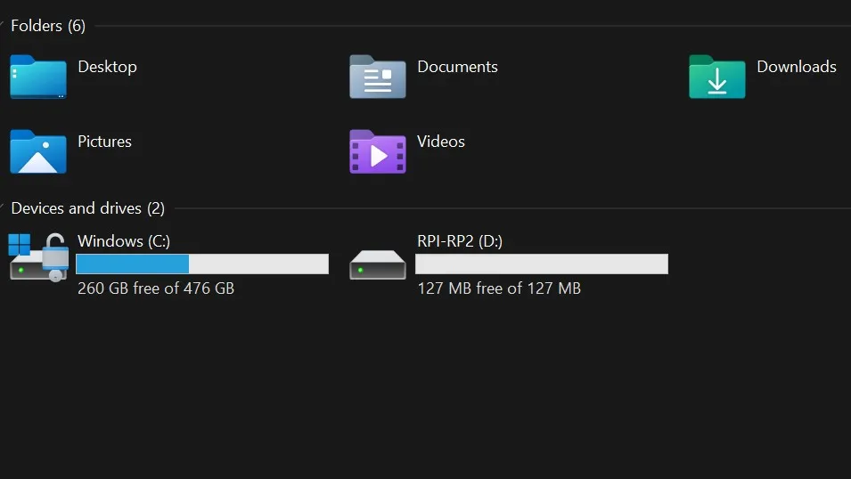
3. Your Pico will mount as a Mass Storage Device with the label RPI-RP2. Copy and paste the UF2 file inside this volume.
Upon successfully copying, your device will reboot, and the volume RPI-RP2 will disappear from your drive list. Congratulations! Your Pico is now running MicroPython. You can now use the REPL to interact with your Pico via USB.
Installation of Thonny IDE and Using REPL
- Go to thonny.org. Download the version suitable for your OS from the website. I installed version 3.3.13 for Windows. This version of Thonny IDE has Python 3.7 built-in. Install the IDE once the download completes.
- While installing, accept the license agreement, set the destination location of Thonny, set the desktop shortcut, and finally click on the Install button. Click on Finish in the last step and launch Thonny.
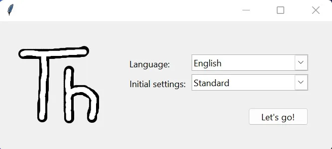
- Upon opening the IDE for the first time, set the Initial settings section to ‘Standard‘ and click the ‘Let’s Go‘ button.
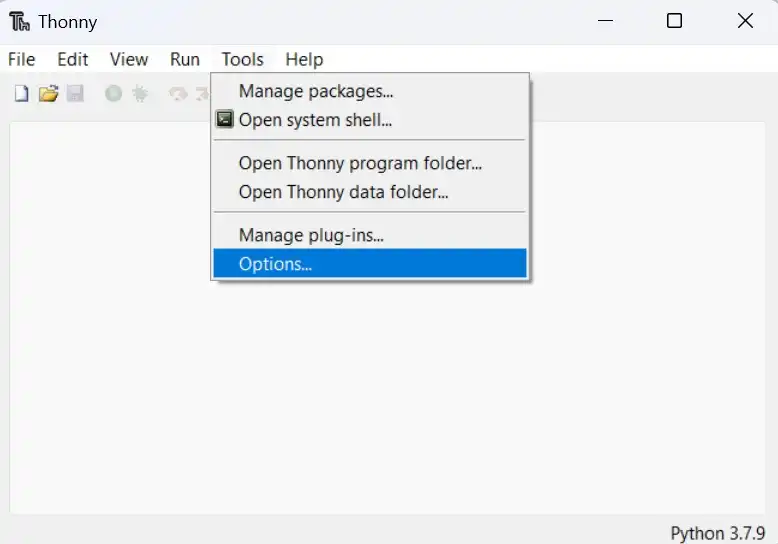
- Go to Tools>Options using the top toolbar menu.
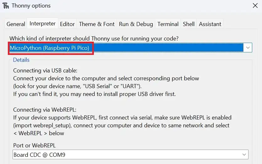
- Go to the Interpreter section and set the interpreter to use MicroPython on Raspberry Pi Pico. Also, ensure that you select the correct port for Pico.
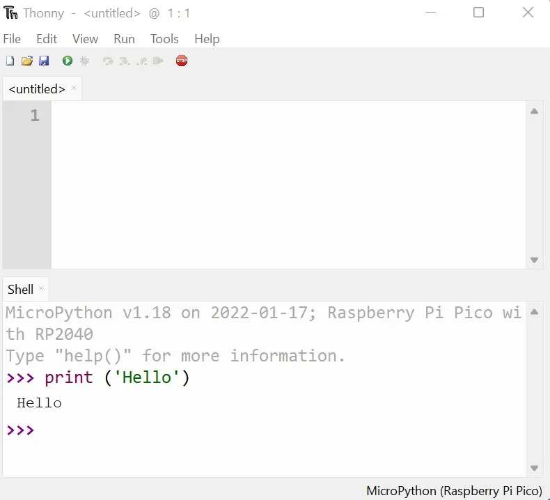
- Type
print ('Hello')in the shell of Thonny IDE. You should see “Hello” printed on the shell, as shown in the screenshot below.
Blink The Onboard LED with MicroPython
Raspberry Pi Pico has an onboard LED connected to Pin 25. In the case of Pico W, the LED is connected to a pin on the CYW4343 chip. We will now try to blink this LED by writing a simple Python program.
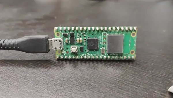
- Connect your Pico to your computer via USB. (Do not press BOOTSEL as we did earlier).
- Open Thonny. Copy the following code and paste it into your main editing space in Thonny. Remember, Python uses indentation. Use proper indentation while typing your code. The following code is for Raspberry Pi Pico W.
from machine import Pin
import time
led = Pin("LED", Pin.OUT)
while True:
    led.low()
    time.sleep_ms(500)
    led.high()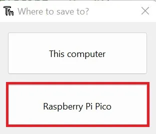
time.sleep_ms(500)Code language: Python (python)- Click on File> Save as from the top toolbar and select Raspberry Pi Pico as the save location.
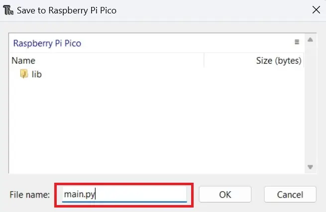
- Save the file as main.py Press OK to save.
The onboard LED on your Pico should now start blinking.
Code explained:
- First, we import two libraries, the
machineand thetimelibrary.
- The
machinelibrary has specific functions that help us interact with the microcontroller’s hardware. The time library has functions that can fetch the current date/time and can help us to set delays within code execution.
led = Pin("LED", Pin.OUT)sets the pin connected to the onboard LED as an output pin.
led.high()will send 3.3V to the output pin of Pico which is connected to an LED.
led.low()will turn off the LED by grounding the pin.
time.sleep_ms(500)will put the microcontroller to sleep for 500 milliseconds.
The LED will keep on toggling between the high and low states at an interval of 500 milliseconds. Try experimenting with the delay times. For example, typing led.sleep(1) will introduce a delay of 1 second.
Program Raspberry Pi Pico Using uPyCraft IDE
Users can also use the uPyCraft IDE to write and upload scripts to their microcontroller. It is another beginner-friendly and easy-to-use IDE. Let us look at how to get started with uPyCraft IDE on Raspberry Pi Pico.
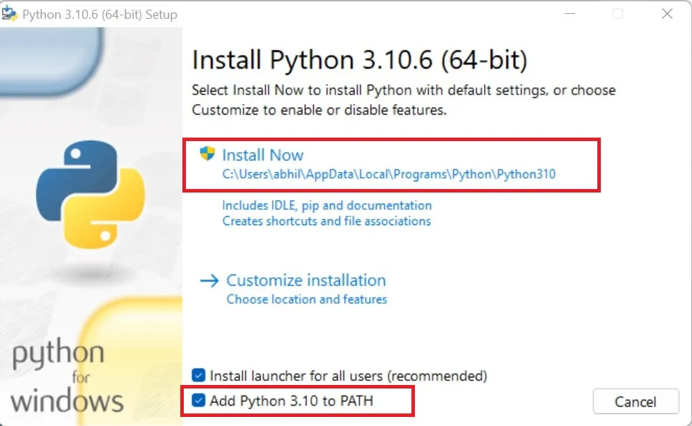
- First, we need to have Python installed on our computer. If you don’t have it already, you can get the latest version by visiting https://www.python.org/downloads/. Download the latest version for your operating system.
- Open the Python installation file. Make sure to tick “Add Python to path“. Then click Install Now.
- After Python successfully installs, we can install the uPyCraft IDE. You can find the installation file by visiting https://github.com/DFRobot/uPyCraft. Download one of the latest versions for your OS. You can also download the IDE from this Google Drive link of version 1.1 of the IDE that I have shared for public access.
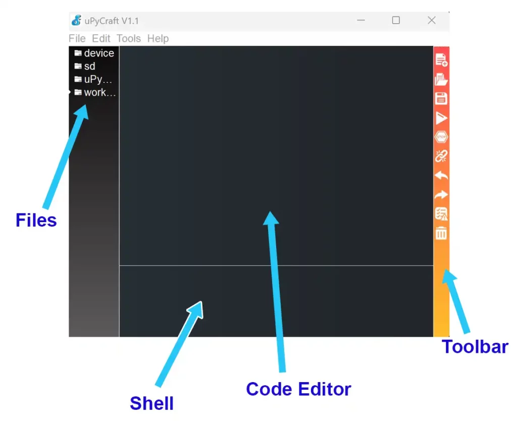
- Opening the uPyCraft IDE file will show a window as described in the image below.
- Connect your Raspberry Pi Pico to your computer via USB data cable.
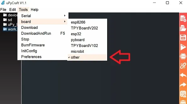
- From the top toolbar of the IDE, click on Tools>board>other.
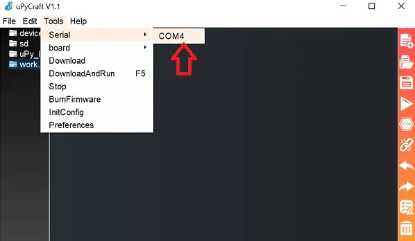
- Then click Tools>Serial and select the COM Port that is shown. In my case, COM4 was displayed.
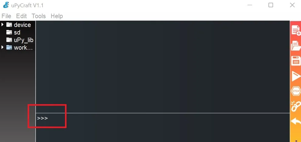
- If the steps were followed correctly, three arrows >>> will show up in the terminal window, meaning a successful connection has been established with Pico. If not, then reconnect your Pico board to computer by disconnecting and reconnecting the USB cable.
- To write a new program, click File>New and paste the following code in the blank space. The code is the same that we wrote in the previous steps.
from machine import Pin
import time
led = Pin("LED", Pin.OUT)
while True:
    led.low()
    time.sleep_ms(500)
    led.high()
    time.sleep_ms(500)Code language: JavaScript (javascript)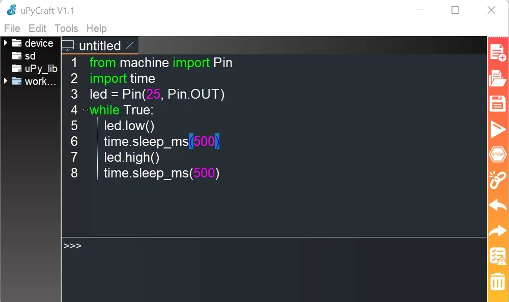
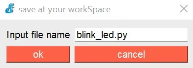
- Click File>Save or use the Ctrl+S shortcut to save the code. A pop-up window will ask you to enter the file name. Enter any filename with a ‘.py’ extension. For example, I named the file blink_led.py. Press ok when done.
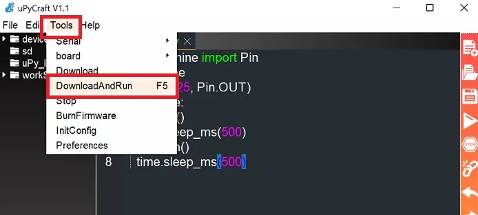
- To send the code to Pico, go to Tools>DownloadAndRun or press F5.
The onboard LED on Pico must now start blinking.
Raspberry Pi Pico Projects To Get Started
Here are some projects you can try next on your Raspberry Pi Pico:
Basic Guides
- Raspberry Pi Pico & Pico W Pinout Guide – All Pins Explained
- Raspberry Pi Pico Interrupts Tutorial Using MicroPython.
- Raspberry Pi Pico PWM Guide.
- Raspberry Pi Pico ADC Guide-MicroPython Example In RP2040 Using A Potentiometer.
- RPi Pico W: Save Data to Flash Permanently Using MicroPython.
Communication Interface Guides
- Raspberry Pi Pico W Bluetooth (BLE) using MicroPython | Point-to-Point Communication
- Raspberry Pi Pico Serial Communication Tutorial With Example.
- Raspberry Pi Pico I2C Communication Guide With Examples.
Sensor Guides
- Raspberry Pi Pico Onboard Temperature Sensor Tutorial Using MicroPython.
- Raspberry Pi Pico Ultrasonic Sensor(HC-SR04) Interfacing.
- Raspberry Pi Pico BMP280 Tutorial-Interface Using MicroPython.
- Use BME280 With Raspberry Pi Pico W – MicroPython Code
- Raspberry Pi Pico DHT11 Interfacing Guide Using MicroPython.
- Raspberry Pi Pico DHT22(AM2302) Interfacing Tutorial.
How to Run MicroPython Script on Startup In Pico?
To start a MicroPython script on power-up, we need to save it as main.py in the onboard flash memory of Raspberry Pi Pico.
Frequently Asked Questions (FAQs)
If your script is running, stop it by clicking the red stop button on the top toolbar of Thonny. Now, click on File>Save as>Raspberry Pi Pico. Set the file name to main.py and click OK. Now, if you disconnect and reconnect your Pico to your computer, or an external power supply, the script main.py will start executing at power-up
How to Reset Raspberry Pi Pico
Raspberry Pi Pico can be easily reset to the factory state by flashing a special UF2 file. More about this is described in our article to reset Raspberry Pi Pico.
Is Raspberry Pi Pico a Computer?
A computer is defined as a digital machine that can automatically carry out arithmetic and logical operations in a sequence. As Raspberry Pi Pico can process and store digital data, you can call it a computer. More specifically, it is a microcontroller development board.
Based around the RP2040 microcontroller, it has some peripherals that make it easier to program and interact with the microcontroller. But Pico is far less powerful than our mobile devices or desktop PCs.
It does not come with ready-made USB ports to connect devices such as a mouse, keyboard, or monitor. Pico is designed for low-power computing applications, such as monitoring a motion sensor or measuring object distances.
What is Raspberry Pi Pico Used For?
This tiny microcontroller has a variety of uses for hobbyists and engineers. Some common uses of Raspberry Pi Pico include – Home automation, Robotics, the Internet of Things(IoT), data logging using sensors, etc.
Does Raspberry Pi Pico Have Wi-Fi?
The newer version released in 2022 i.e. Raspberry Pi Pico W has Wi-Fi. But the earlier versions do not have it. In order to send or receive data to the original Raspberry Pi Pico via the internet or a web browser, we need to interface it with Wi-Fi modules such as ESP8266 or ESP32.
“Couldn’t find the device automatically” Error in Thonny IDE
You might have encountered this problem with an error message saying “Couldn’t find the device automatically. Check the connection (making sure the device is not in bootloader mode) or choose
“Configure interpreter” in the interpreter menu (bottom-right corner of the window)
to select specific port or another interpreter.”
To get around this error, ensure your Raspberry Pi Pico is connected to your computer via USB. Check the USB cable for faults. If the connection is OK, click the ‘Stop‘ button on the top toolbar. Now you should be able to upload code to your Pico.
Wrapping Up
We used MicroPython throughout this tutorial, but you can also use C/C++ to develop programs for Pico. You can read about it in our guide – How to Program Raspberry Pi Pico using Arduino IDE. To learn more about programming the Pico using MicroPython, you can visit their official documentation via this link.
Leave a Reply