In this tutorial, learn how to read the inbuilt/onboard temperature sensor in Raspberry Pi Pico. First, we shall write a simple MicroPython script to display temperature values. Interfacing with an OLED display is also explained.
The ADC on Pico will be used to read the temperature. So let us get a brief overview of the ADC before we proceed.
The ADC in Raspberry Pi Pico & Pico W
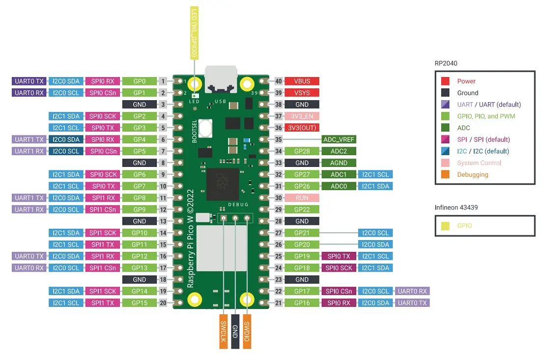
Raspberry Pi Pico & Pico W features the RP2040 microcontroller. The RP2040 has a total of 5 ADC(Analog-to-Digital Converter) channels. ADC0, ADC1, ADC2, and ADC3 are connected to GP26, GP27, GP28, and GP29 respectively. These four are 12-bit SAR-based ADCs.
The fifth ADC channel is connected to an internal temperature sensor. These ADCs measure analog voltage in the range of 0-3.3 Volts.
The ADCs have a sampling rate of 500kS/s and use an independent 48Mhz clock for this purpose. Each sample takes 96 clock cycles. So the sampling time taken per sample is (96/48Mhz)=2μS.
The 12-bit ADC register will give us a value ranging from 0 to 4095 (2^12-1). But specific functions in MicroPython can scale the ADC values to give us a 16-bit range. So we can get sensor readings ranging from 0 to 65535 (2^16-1). We shall see this shortly in the code below. The resolution of an ADC is the smallest analog voltage change for which there occurs a change in digital reading.
To know more about the ADC in Raspberry Pi Pico, read our dedicated article: Raspberry Pi Pico ADC Guide.
The Onboard Temperature Sensor on Raspberry Pi Pico
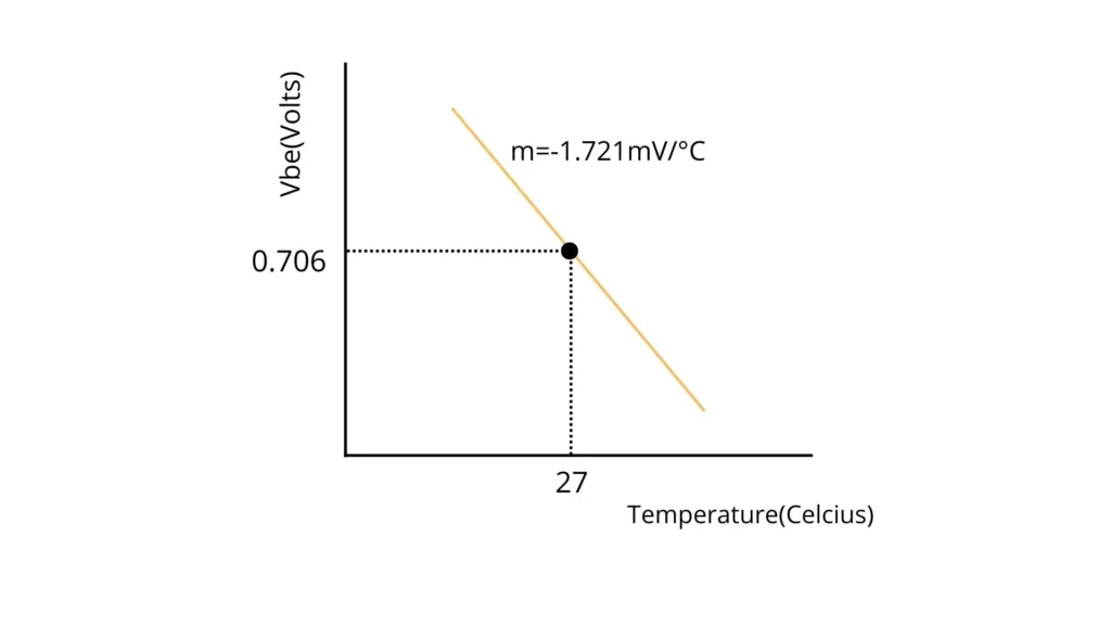
The onboard temperature sensor in Pi Pico uses a clever trick. According to the datasheet of RP20240, “The temperature sensor measures the Vbe voltage of a biased bipolar diode, connected to the fifth ADC channel (AINSEL=4). Typically, Vbe is 0.706V at 27 degrees C, with a slope of -1.721mV per degree”. Using this detail, we will now try to find a mathematical expression to derive temperature based on the Vbe voltage.
If we consider temperature along the X-axis, Voltage(Vbe) along the Y-axis and a gradient of -1.721mV/°C, we can plot a graph as shown below.
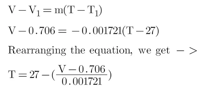
The point-slope form of a linear equation is written as y-y1=m(x-x1). We can form an equation: V-V1=m(T-T1), where V is the Vbe voltage, m is the gradient and T is the temperature. Let us solve this equation and find T.
MicroPython Code to Read Raspberry Pi Pico Temperature Sensor
We shall be using Thonny IDE to upload a MicroPython script to Pi Pico. If you are a beginner, please look at our article Getting Started With Raspberry Pi Pico on Windows to set up and program your Pico. For macOS users, follow our guide to Program Raspberry Pi Pico On macOS Using Thonny IDE. Ensure that the UF2 MicroPython file is already flashed in your Pico before proceeding further with this guide.
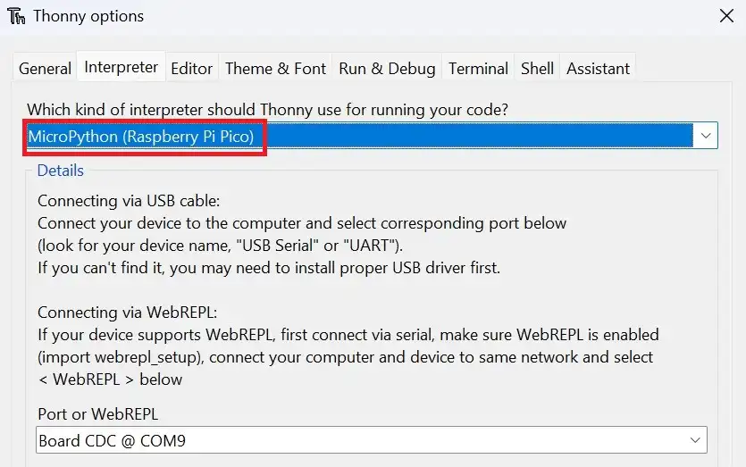
Connect Raspberry Pi Pico W to the computer using a USB cable. Open Thonny IDE and set the interpreter to Raspberry Pi Pico by navigating to Tools>Options>Interpreter.
Create a new file by clicking on File>New and paste the following MicroPython code to read the temperature:
# Source: Electrocredible.com, Language: MicroPython
from machine import ADC
import time
adc = machine.ADC(4)
while True:
ADC_voltage = adc.read_u16() * (3.3 / (65536))
temperature_celcius = 27 - (ADC_voltage - 0.706)/0.001721
temp_fahrenheit=32+(1.8*temperature_celcius)
print("Temperature: {}°C {}°F".format(temperature_celcius,temp_fahrenheit))
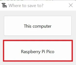
time.sleep_ms(500)Code language: Python (python)Save the MicroPython file by clicking on File>Save as or using the shortcut Ctrl+Shift+S. Select Raspberry Pi Pico on the dialog box that appears to save the code to your Pico W.
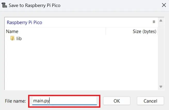
Give the script with a file name “main.py”.
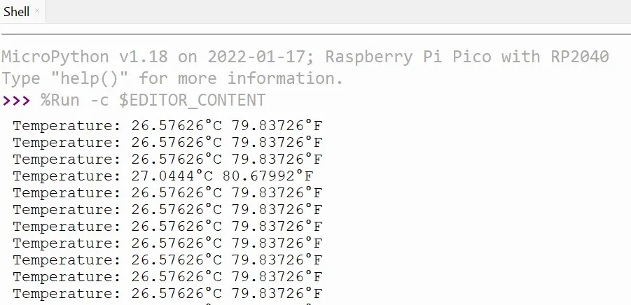
Click the shortcut F5 or the Run button to run the script that you saved to Raspberry Pi Pico W.

The Thonny shell window will display the output shown below when your script starts running.
Also read: Raspberry Pi Pico BME280 Interfacing Guide Using MicroPython
Raspberry Pi Pico Temperature Sensor Code Explained
First, we have to import the ADC and time modules. The ADC module will help us to read the analog voltage values from pins and convert them to digital data. We shall use the time module to introduce delays in our script.
from machine import ADC
import timepyCode language: Python (python)
We create an adc instance to read the voltage from the fifth ADC channel(ADC4 refers to the fifth channel).
adc = machine.ADC(4) Now, we shall read the voltage in the ADC pin. adc.read_u16() will read 16 bits of digital data. As we discussed earlier under the heading The ADC in Raspberry Pi Pico, we will get a reading in the range of 0-65535 for a voltage range of 0V to 3.3V. So, based on the simple unitary method, we multiply the ADC reading with (3.3 / (65536)).
ADC_voltage = adc.read_u16() * (3.3 / (65536))Based on the equation we solved above in this article, we calculate the value for temperature in Celcius and then convert it to Fahrenheit.
temperature_celcius = 27 - (ADC_voltage - 0.706)/0.001721
temp_fahrenheit=32+(1.8*temperature_celcius)Code language: Python (python)
We then print the value of temperature in Celcius and Fahrenheit and introduce a delay of 500 milliseconds. Without this delay, the results will be printed too fast.
print("Temperature: {}°C {}°F".format(temperature_celcius,temp_fahrenheit))
time.sleep_ms(500)Code language: Python (python)
Display Onboard Temperature Sensor Value On OLED Display
Let us write a script to display the Raspberry Pi Pico internal temperature sensor data on a 128×64 SSD1306 OLED display.
Schematic
Connect your Pico to the OLED display as shown in the figure below.
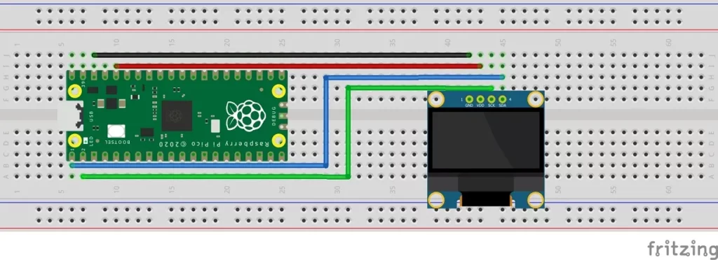
Connection Details:
| Raspberry Pi Pico Pin | OLED Display Pin |
| Pin 1 (GP0) | 4(SDA) |
| Pin 2 (GP1) | 3(SCL) |
| Pin 36(3.3 Volts Out) | 2(VDD) |
| Pin 38(GND) | 1(GND) |
Installation of OLED Library
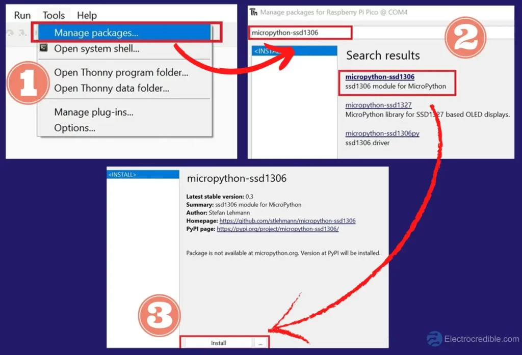
With your Pico connected to the computer, Open Thonny IDE and perform the following steps to install the MicroPython library for SSD1306.
- In Thonny IDE, go to Tools> Manage Packages.
- Type “micropython-ssd1306” on the search bar and press Enter. From the search results, click on the library that you searched for.
- In the next window, click on Install.
Alternatively, copy-paste the following code and save it as ssd1306.py.
# MicroPython SSD1306 OLED driver, I2C and SPI interfaces

from micropython import const
import framebuf


# register definitions
SET_CONTRAST = const(0x81)
SET_ENTIRE_ON = const(0xA4)
SET_NORM_INV = const(0xA6)
SET_DISP = const(0xAE)
SET_MEM_ADDR = const(0x20)
SET_COL_ADDR = const(0x21)
SET_PAGE_ADDR = const(0x22)
SET_DISP_START_LINE = const(0x40)
SET_SEG_REMAP = const(0xA0)
SET_MUX_RATIO = const(0xA8)
SET_COM_OUT_DIR = const(0xC0)
SET_DISP_OFFSET = const(0xD3)
SET_COM_PIN_CFG = const(0xDA)
SET_DISP_CLK_DIV = const(0xD5)
SET_PRECHARGE = const(0xD9)
SET_VCOM_DESEL = const(0xDB)
SET_CHARGE_PUMP = const(0x8D)

# Subclassing FrameBuffer provides support for graphics primitives
# http://docs.micropython.org/en/latest/pyboard/library/framebuf.html
class SSD1306(framebuf.FrameBuffer):
    def __init__(self, width, height, external_vcc):
        self.width = width
        self.height = height
        self.external_vcc = external_vcc
        self.pages = self.height // 8
        self.buffer = bytearray(self.pages * self.width)
        super().__init__(self.buffer, self.width, self.height, framebuf.MONO_VLSB)
        self.init_display()

    def init_display(self):
        for cmd in (
            SET_DISP | 0x00,  # off
            # address setting
            SET_MEM_ADDR,
            0x00,  # horizontal
            # resolution and layout
            SET_DISP_START_LINE | 0x00,
            SET_SEG_REMAP | 0x01,  # column addr 127 mapped to SEG0
            SET_MUX_RATIO,
            self.height - 1,
            SET_COM_OUT_DIR | 0x08,  # scan from COM[N] to COM0
            SET_DISP_OFFSET,
            0x00,
            SET_COM_PIN_CFG,
            0x02 if self.width > 2 * self.height else 0x12,
            # timing and driving scheme
            SET_DISP_CLK_DIV,
            0x80,
            SET_PRECHARGE,
            0x22 if self.external_vcc else 0xF1,
            SET_VCOM_DESEL,
            0x30,  # 0.83*Vcc
            # display
            SET_CONTRAST,
            0xFF,  # maximum
            SET_ENTIRE_ON,  # output follows RAM contents
            SET_NORM_INV,  # not inverted
            # charge pump
            SET_CHARGE_PUMP,
            0x10 if self.external_vcc else 0x14,
            SET_DISP | 0x01,
        ):  # on
            self.write_cmd(cmd)
        self.fill(0)
        self.show()

    def poweroff(self):
        self.write_cmd(SET_DISP | 0x00)

    def poweron(self):
        self.write_cmd(SET_DISP | 0x01)

    def contrast(self, contrast):
        self.write_cmd(SET_CONTRAST)
        self.write_cmd(contrast)

    def invert(self, invert):
        self.write_cmd(SET_NORM_INV | (invert & 1))

    def show(self):
        x0 = 0
        x1 = self.width - 1
        if self.width == 64:
            # displays with width of 64 pixels are shifted by 32
            x0 += 32
            x1 += 32
        self.write_cmd(SET_COL_ADDR)
        self.write_cmd(x0)
        self.write_cmd(x1)
        self.write_cmd(SET_PAGE_ADDR)
        self.write_cmd(0)
        self.write_cmd(self.pages - 1)
        self.write_data(self.buffer)


class SSD1306_I2C(SSD1306):
    def __init__(self, width, height, i2c, addr=0x3C, external_vcc=False):
        self.i2c = i2c
        self.addr = addr
        self.temp = bytearray(2)
        self.write_list = [b"\x40", None]  # Co=0, D/C#=1
        super().__init__(width, height, external_vcc)

    def write_cmd(self, cmd):
        self.temp[0] = 0x80  # Co=1, D/C#=0
        self.temp[1] = cmd
        self.i2c.writeto(self.addr, self.temp)

    def write_data(self, buf):
        self.write_list[1] = buf
        self.i2c.writevto(self.addr, self.write_list)


class SSD1306_SPI(SSD1306):
    def __init__(self, width, height, spi, dc, res, cs, external_vcc=False):
        self.rate = 10 * 1024 * 1024
        dc.init(dc.OUT, value=0)
        res.init(res.OUT, value=0)
        cs.init(cs.OUT, value=1)
        self.spi = spi
        self.dc = dc
        self.res = res
        self.cs = cs
        import time

        self.res(1)
        time.sleep_ms(1)
        self.res(0)
        time.sleep_ms(10)
        self.res(1)
        super().__init__(width, height, external_vcc)

    def write_cmd(self, cmd):
        self.spi.init(baudrate=self.rate, polarity=0, phase=0)
        self.cs(1)
        self.dc(0)
        self.cs(0)
        self.spi.write(bytearray([cmd]))
        self.cs(1)

    def write_data(self, buf):
        self.spi.init(baudrate=self.rate, polarity=0, phase=0)
        self.cs(1)
        self.dc(1)
        self.cs(0)
        self.spi.write(buf)
        self.cs(1)
Code language: Python (python)
Code to Display Temperature on OLED Display
After ensuring that the OLED library has been properly installed, copy and paste the following script into a new window in Thonny IDE.
# Source: Electrocredible.com, Language: MicroPython
from machine import ADC, Pin, I2C
from ssd1306 import SSD1306_I2C
import time
adc = machine.ADC(4)
WIDTH =128
HEIGHT= 64
i2c=I2C(0,scl=Pin(1),sda=Pin(0),freq=200000)
oled = SSD1306_I2C(WIDTH,HEIGHT,i2c)
while True:
    oled.fill(0)
    ADC_voltage = adc.read_u16() * (3.3 / (65536))
    temperature_celcius = 27 - (ADC_voltage - 0.706)/0.001721
    temp_fahrenheit=32+(1.8*temperature_celcius)
    oled.text("Temperature:",0,10)
    oled.text(str(int(temperature_celcius)), 95, 10)
    oled.text("C",110,10)
    oled.show()
    time.sleep_ms(500)Code language: Python (python)
If you want to understand how this part of the script works, you can view the explanation here.
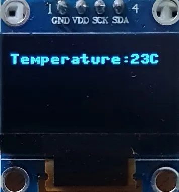
Run the script and save it on RPi Pico with a “.py” filename extension. You should see the temperature value displayed in the OLED display as shown in the image below.
Conclusion
Raspberry Pi Pico’s onboard temperature sensor may not be accurate. Depending on the reference voltage, the temperature reading may vary. Raspberry Pi Pico uses 3.3V as a reference voltage for the ADC. A change of 1% in this reference voltage can vary the temperature reading by as much as 4°C. To improve the accuracy, adding an external reference voltage(such as TL431 IC) to the Pico is recommended.
DHT22 is a more reliable temperature and humidity sensor, discussed in our article Raspberry Pi Pico DHT22(AM2302) Interfacing Tutorial. DHT11 is another cheap and popular temperature & humidity sensor. Its humidity sensing range is less than DHT22. We have explained its interfacing details in the article Raspberry Pi Pico DHT11 MicroPython – Easy Interfacing Guide.
BME280 and BMP280 are some other alternatives. These sensors are a little more expensive than the other options but provide greater range, accuracy, and precision. Read more about their usage:
Hope you found this guide on Raspberry Pi Pico temperature sensor helpful. To share your thoughts, please comment below.
Leave a Reply