In this article, you will learn how to use the I2C communication using MicroPython code. Examples are discussed using ESP32 and Raspberry Pi Pico development boards. MicroPython examples will be shown to:
- Scan devices connected to an I2C bus.
- Read and write I2C data.
- Connect multiple devices to the same I2C bus.
Overview of I2C Communication Interface
I2C is a Serial Communication Protocol invented by Phillips. I2C is commonly referred to as I2C or IIC. This mode of communication uses two bidirectional lines.
The I2C bus identifies peripherals (nodes) with 7-bit addresses. Each node can act as either a master or a slave while communicating. The master device usually generates the clock signal in the SCL line. Multiple slave devices can communicate with a single master device.
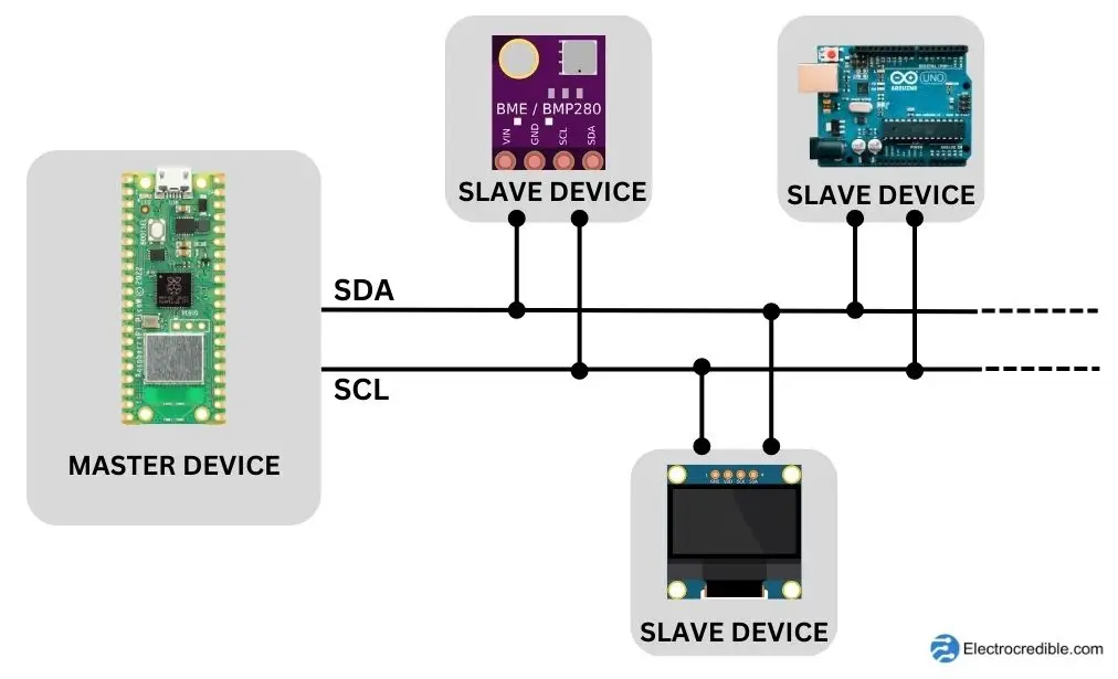
Multiple devices can be connected to the same SDA and SCL lines in a “daisy-chain” way. As every device on the bus has a distinct address, the master can choose which particular device it shall interact with.
I2C shares many similarities with TWI(Two-Wire Protocol). To avoid legal issues, the term TWI is used by some vendors. There are a few differences between the two protocols, for example, TWI does not use a START byte in its data packet. In most situations, they can be used interchangeably.
I2C Pins & I2C Bus
The main signal wires in an I2C bus are the Serial Data Line (SDA) and the Serial Clock Line (SCL).
- Serial Data Line (SDA):
- The SDA pin is used for bidirectional data transfer between the master and slave devices on the I2C bus.
- It carries information such as commands, addresses, and data.
- Serial Clock Line (SCL):
- The SCL pin synchronizes the data transfer between devices on the I2C bus.
- It acts as a clock signal that regulates the timing of data transmission.
The SDA and SCL lines are “open-drain” or “open-collector” lines, devices can pull it low, but they cannot drive it high. Pull-up resistors must be connected to prevent a “floating state” of these lines. The value of the pull-up resistors depends on the bus’s capacitance and the desired communication speed. Common values are in the range of 1kΩ to 10kΩ.
Voltage Compatibility
I2C works with a wide range of voltage levels. But you must be careful not to interface a 5V device with a 3.3V device as it may cause damage. Use a logic level shifter to shift the voltages while interfacing.
MicroPython Methods for I2C
Here are some I2C methods that you can use to communicate with I2C devices using MicroPython easily:
i2c = I2C(0): Default statement to declare ani2cobject of theI2Cclass.i2c.scan(): Scan for peripherals, and returns a list of 7-bit addresses.i2c.writeto(42, b'123'): Write 3 bytes to the device. The device’s address is 42.i2c.readfrom(0x3a, 4): Read 4 bytes from the peripheral that has a 7-bit address of 0x3a.i2c.start(): Generate a START condition on the bus.i2c.stop(): Generate a STOP condition on the bus.

Scan I2C Devices using MicroPython Code
As I2C devices have unique addresses, knowing their addresses will help us to interface with one or more devices. Scanning I2C devices also helps to know if the wiring is correct.
Consider the example of a microcontroller connected to a sensor that can communicate via. We can use the following code to scan the I2C address of the sensor.
import machine
sdaPIN=machine.Pin(0)
sclPIN=machine.Pin(1)
i2c=machine.I2C(0,sda=sdaPIN, scl=sclPIN, freq=400000)
devices = i2c.scan()
if len(devices) != 0:
    print('Number of I2C devices found=',len(devices))
    for device in devices:
        print("Device Hexadecimel Address= ",hex(device))
else:
    print("No device found")Code language: PHP (php)
The example in the next section below demonstrates how to use this code to scan I2C devices. If multiple devices are connected to an I2C bus, the addresses of every device will be printed.
MicroPython I2C Example: Interface a Sensor
Let us try a simple example of how sensors can be interfaced with an ESP32 development board using I2C and MicroPython code.
First, ensure that MicroPython firmware has been flashed to your ESP32. Our guides to flash and run MicroPython on ESP32 using uPyCraft IDE and getting started with ESP32 on Thonny IDE are helpful resources.
ESP32 has two hardware I2C modules which are multiplexed to the GPIOs. The BME280 environmental sensor is used in this example to demonstrate how we can read data from a sensor using I2C.
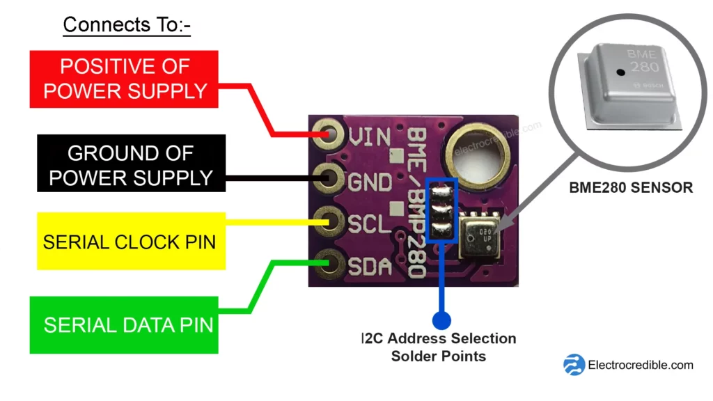
BME280 is a 3-in-one environmental sensor by Bosch Sensortech. It outputs digital data containing information about temperature, pressure, and humidity. It is commonly available in the form of breakout board modules. The GY-BME280 module comes with 4 pins for connection as shown below.
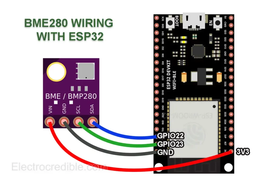
Wiring ESP32 with BME280
This project uses an ESP-WROOM-32 development board but you can choose any other board. Note that the pins used may differ for other ESP32 boards.
I2C Connection details
| ESP32 Pin | BME280 Pin |
| GPIO 22 | SDA |
| GPIO 23 | SCL |
| 3V3 | VIN |
| GND | GND |
Scan I2C Address
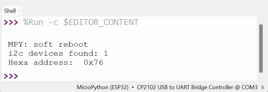
After connecting GPIO22 and GPIO23 of ESP32 to BME280 SDA and SDA pins respectively, run the following MicroPython code to scan and find the address of the BME280 sensor:
# Import the machine module for hardware access
import machine

# Initialize the SDA pin for I2C communication
sdaPIN = machine.Pin(22)

# Initialize the SCL pin for I2C communication
sclPIN = machine.Pin(23)

# Initialize the I2C interface with the specified pins and frequency
i2c = machine.I2C(0, sda=sdaPIN, scl=sclPIN, freq=400000)

# Scan for devices connected to the I2C bus
devices = i2c.scan()

# Check if any devices are found
if len(devices) == 0:
    # If no devices are found, print a message
    print("No I2C devices found!")
else:
    # If devices are found, print the number of devices found
    print('I2C devices found:', len(devices))
    # Iterate through each device found and print its hexadecimal address
    for device in devices:
        print("Hexadecimal address:", hex(device))Code language: PHP (php)
The screenshot below demonstrates the output in the shell of Thonny IDE showing the hexadecimal address of the BME280 found after scanning.
Install BME280 MicroPython Library
BME280 can be interfaced easily using a MicroPython library that helps us to read it using simple methods.
Upload the following code to your ESP32 and name the code file as “bme280.py“.
# Authors: Paul Cunnane 2016, Peter Dahlebrg 2016
#
# This module borrows from the Adafruit BME280 Python library. Original
# Copyright notices are reproduced below.
#
# Those libraries were written for the Raspberry Pi. This modification is
# intended for the MicroPython and esp8266 boards.
#
# Copyright (c) 2014 Adafruit Industries
# Author: Tony DiCola
#
# Based on the BMP280 driver with BME280 changes provided by
# David J Taylor, Edinburgh (www.satsignal.eu)
#
# Based on Adafruit_I2C.py created by Kevin Townsend.
#
# Permission is hereby granted, free of charge, to any person obtaining a copy
# of this software and associated documentation files (the "Software"), to deal
# in the Software without restriction, including without limitation the rights
# to use, copy, modify, merge, publish, distribute, sublicense, and/or sell
# copies of the Software, and to permit persons to whom the Software is
# furnished to do so, subject to the following conditions:
#
# The above copyright notice and this permission notice shall be included in
# all copies or substantial portions of the Software.
#
# THE SOFTWARE IS PROVIDED "AS IS", WITHOUT WARRANTY OF ANY KIND, EXPRESS OR
# IMPLIED, INCLUDING BUT NOT LIMITED TO THE WARRANTIES OF MERCHANTABILITY,
# FITNESS FOR A PARTICULAR PURPOSE AND NONINFRINGEMENT. IN NO EVENT SHALL THE
# AUTHORS OR COPYRIGHT HOLDERS BE LIABLE FOR ANY CLAIM, DAMAGES OR OTHER
# LIABILITY, WHETHER IN AN ACTION OF CONTRACT, TORT OR OTHERWISE, ARISING FROM,
# OUT OF OR IN CONNECTION WITH THE SOFTWARE OR THE USE OR OTHER DEALINGS IN
# THE SOFTWARE.


import time
from ustruct import unpack, unpack_from
from array import array

# BME280 default address.
BME280_I2CADDR = 0x76

# Operating Modes
BME280_OSAMPLE_1 = 1
BME280_OSAMPLE_2 = 2
BME280_OSAMPLE_4 = 3
BME280_OSAMPLE_8 = 4
BME280_OSAMPLE_16 = 5

BME280_REGISTER_CONTROL_HUM = 0xF2
BME280_REGISTER_CONTROL = 0xF4


class BME280:

    def __init__(self,
                 mode=BME280_OSAMPLE_1,
                 address=BME280_I2CADDR,
                 i2c=None,
                 **kwargs):
        # Check that mode is valid.
        if mode not in [BME280_OSAMPLE_1, BME280_OSAMPLE_2, BME280_OSAMPLE_4,
                        BME280_OSAMPLE_8, BME280_OSAMPLE_16]:
            raise ValueError(
                'Unexpected mode value {0}. Set mode to one of '
                'BME280_ULTRALOWPOWER, BME280_STANDARD, BME280_HIGHRES, or '
                'BME280_ULTRAHIGHRES'.format(mode))
        self._mode = mode
        self.address = address
        if i2c is None:
            raise ValueError('An I2C object is required.')
        self.i2c = i2c

        # load calibration data
        dig_88_a1 = self.i2c.readfrom_mem(self.address, 0x88, 26)
        dig_e1_e7 = self.i2c.readfrom_mem(self.address, 0xE1, 7)
        self.dig_T1, self.dig_T2, self.dig_T3, self.dig_P1, \
            self.dig_P2, self.dig_P3, self.dig_P4, self.dig_P5, \
            self.dig_P6, self.dig_P7, self.dig_P8, self.dig_P9, \
            _, self.dig_H1 = unpack("<HhhHhhhhhhhhBB", dig_88_a1)

        self.dig_H2, self.dig_H3 = unpack("<hB", dig_e1_e7)
        e4_sign = unpack_from("<b", dig_e1_e7, 3)[0]
        self.dig_H4 = (e4_sign << 4) | (dig_e1_e7[4] & 0xF)

        e6_sign = unpack_from("<b", dig_e1_e7, 5)[0]
        self.dig_H5 = (e6_sign << 4) | (dig_e1_e7[4] >> 4)

        self.dig_H6 = unpack_from("<b", dig_e1_e7, 6)[0]

        self.i2c.writeto_mem(self.address, BME280_REGISTER_CONTROL,
                             bytearray([0x3F]))
        self.t_fine = 0

        # temporary data holders which stay allocated
        self._l1_barray = bytearray(1)
        self._l8_barray = bytearray(8)
        self._l3_resultarray = array("i", [0, 0, 0])

    def read_raw_data(self, result):
        """ Reads the raw (uncompensated) data from the sensor.

            Args:
                result: array of length 3 or alike where the result will be
                stored, in temperature, pressure, humidity order
            Returns:
                None
        """

        self._l1_barray[0] = self._mode
        self.i2c.writeto_mem(self.address, BME280_REGISTER_CONTROL_HUM,
                             self._l1_barray)
        self._l1_barray[0] = self._mode << 5 | self._mode << 2 | 1
        self.i2c.writeto_mem(self.address, BME280_REGISTER_CONTROL,
                             self._l1_barray)

        sleep_time = 1250 + 2300 * (1 << self._mode)
        sleep_time = sleep_time + 2300 * (1 << self._mode) + 575
        sleep_time = sleep_time + 2300 * (1 << self._mode) + 575
        time.sleep_us(sleep_time)  # Wait the required time

        # burst readout from 0xF7 to 0xFE, recommended by datasheet
        self.i2c.readfrom_mem_into(self.address, 0xF7, self._l8_barray)
        readout = self._l8_barray
        # pressure(0xF7): ((msb << 16) | (lsb << 8) | xlsb) >> 4
        raw_press = ((readout[0] << 16) | (readout[1] << 8) | readout[2]) >> 4
        # temperature(0xFA): ((msb << 16) | (lsb << 8) | xlsb) >> 4
        raw_temp = ((readout[3] << 16) | (readout[4] << 8) | readout[5]) >> 4
        # humidity(0xFD): (msb << 8) | lsb
        raw_hum = (readout[6] << 8) | readout[7]

        result[0] = raw_temp
        result[1] = raw_press
        result[2] = raw_hum

    def read_compensated_data(self, result=None):
        """ Reads the data from the sensor and returns the compensated data.

            Args:
                result: array of length 3 or alike where the result will be
                stored, in temperature, pressure, humidity order. You may use
                this to read out the sensor without allocating heap memory

            Returns:
                array with temperature, pressure, humidity. Will be the one from
                the result parameter if not None
        """
        self.read_raw_data(self._l3_resultarray)
        raw_temp, raw_press, raw_hum = self._l3_resultarray
        # temperature
        var1 = ((raw_temp >> 3) - (self.dig_T1 << 1)) * (self.dig_T2 >> 11)
        var2 = (((((raw_temp >> 4) - self.dig_T1) *
                  ((raw_temp >> 4) - self.dig_T1)) >> 12) * self.dig_T3) >> 14
        self.t_fine = var1 + var2
        temp = (self.t_fine * 5 + 128) >> 8

        # pressure
        var1 = self.t_fine - 128000
        var2 = var1 * var1 * self.dig_P6
        var2 = var2 + ((var1 * self.dig_P5) << 17)
        var2 = var2 + (self.dig_P4 << 35)
        var1 = (((var1 * var1 * self.dig_P3) >> 8) +
                ((var1 * self.dig_P2) << 12))
        var1 = (((1 << 47) + var1) * self.dig_P1) >> 33
        if var1 == 0:
            pressure = 0
        else:
            p = 1048576 - raw_press
            p = (((p << 31) - var2) * 3125) // var1
            var1 = (self.dig_P9 * (p >> 13) * (p >> 13)) >> 25
            var2 = (self.dig_P8 * p) >> 19
            pressure = ((p + var1 + var2) >> 8) + (self.dig_P7 << 4)

        # humidity
        h = self.t_fine - 76800
        h = (((((raw_hum << 14) - (self.dig_H4 << 20) -
                (self.dig_H5 * h)) + 16384)
              >> 15) * (((((((h * self.dig_H6) >> 10) *
                            (((h * self.dig_H3) >> 11) + 32768)) >> 10) +
                          2097152) * self.dig_H2 + 8192) >> 14))
        h = h - (((((h >> 15) * (h >> 15)) >> 7) * self.dig_H1) >> 4)
        h = 0 if h < 0 else h
        h = 419430400 if h > 419430400 else h
        humidity = h >> 12

        if result:
            result[0] = temp
            result[1] = pressure
            result[2] = humidity
            return result

        return array("i", (temp, pressure, humidity))

    @property
    def values(self):
        """ human readable values """

        t, p, h = self.read_compensated_data()

        p = p // 256
        pi = p // 100
        pd = p - pi * 100

        hi = h // 1024
        hd = h * 100 // 1024 - hi * 100
        return ("{}C".format(t / 100), "{}.{:02d}hPa".format(pi, pd),
                "{}.{:02d}%".format(hi, hd))
Code to read I2C data from BME280
The following code will read the temperature, humidity, and pressure data from BME280 over I2C, and print it in the shell of your IDE.
from machine import Pin, I2C
import time
import bme280
i2c=I2C(0,sda=Pin(22), scl=Pin(23), freq=100000)
bme = bme280.BME280(i2c=i2c)
def read_bme():
t, p, h = bme.read_compensated_data()
temp=t/100
pres = (p / 256)/100
hum = h / 1024
return temp, pres, hum
while True:
temp, pres, hum= read_bme()
print ("Temperature= {}C".format(temp), "Pressure= {:.2f}hPa".format(pres),
"RH= {:.2f}%".format(hum))
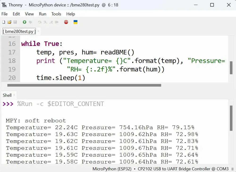
time.sleep(1)Code language: JavaScript (javascript)For more information on how the code works, read our tutorial on reading BME280 with Raspberry Pi Pico & MicroPython Code.
Upon running the code above, the following output is seen in the shell of Thonny IDE:
Connect Multiple I2C Devices Using MicroPython
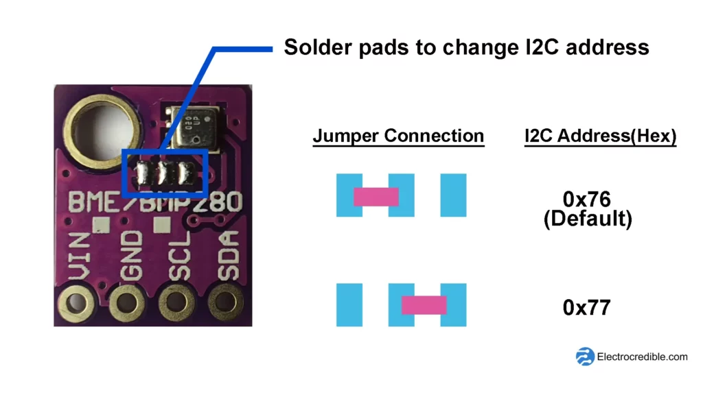
Multiple devices can be connected to the same I2C. If you are connecting the same kind of sensor/device, ensure that the addresses of the devices are different.
For example, you can change the I2C address of a BME280 sensor by changing the connections in the onboard solder pads.
Wiring Multiple I2C Devices
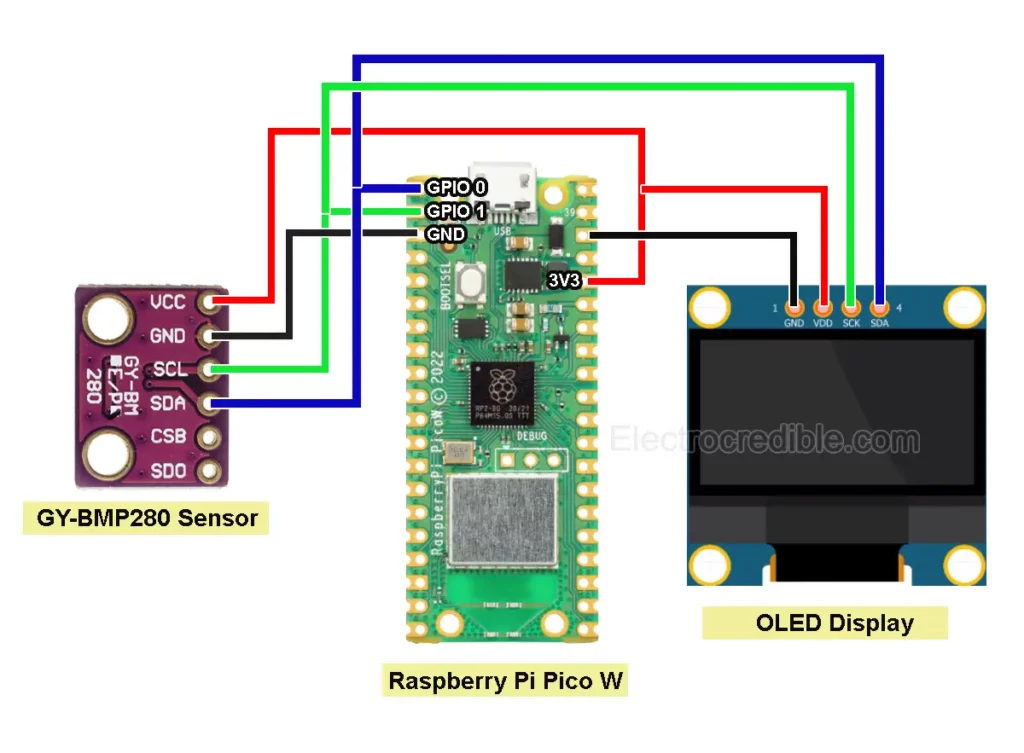
An example below shows how we can interface the following devices at once using I2C:
- A BMP280 temperature and pressure sensor (GY-BMP280 module shown here).
- Raspberry Pi Pico development board.
- SSD1306 OLED display
The diagram below shows the BMP280 temperature and pressure sensor wiring with an OLED display and a Raspberry Pi Pico.
To interface these I2C devices together, we need to install libraries for the sensor and the display. Also, MicroPython firmware has to be flashed to Raspberry Pi Pico.
Follow our easy guide to Program Raspberry Pi Pico with MicroPython.
BMP280 MicroPython Library
Save the following MicroPython library to your microcontroller and name the code file bmp280.py.
from micropython import const
from ustruct import unpack as unp

# Author David Stenwall Wahlund (david at dafnet.se)

# Power Modes
BMP280_POWER_SLEEP = const(0)
BMP280_POWER_FORCED = const(1)
BMP280_POWER_NORMAL = const(3)

BMP280_SPI3W_ON = const(1)
BMP280_SPI3W_OFF = const(0)

BMP280_TEMP_OS_SKIP = const(0)
BMP280_TEMP_OS_1 = const(1)
BMP280_TEMP_OS_2 = const(2)
BMP280_TEMP_OS_4 = const(3)
BMP280_TEMP_OS_8 = const(4)
BMP280_TEMP_OS_16 = const(5)

BMP280_PRES_OS_SKIP = const(0)
BMP280_PRES_OS_1 = const(1)
BMP280_PRES_OS_2 = const(2)
BMP280_PRES_OS_4 = const(3)
BMP280_PRES_OS_8 = const(4)
BMP280_PRES_OS_16 = const(5)

# Standby settings in ms
BMP280_STANDBY_0_5 = const(0)
BMP280_STANDBY_62_5 = const(1)
BMP280_STANDBY_125 = const(2)
BMP280_STANDBY_250 = const(3)
BMP280_STANDBY_500 = const(4)
BMP280_STANDBY_1000 = const(5)
BMP280_STANDBY_2000 = const(6)
BMP280_STANDBY_4000 = const(7)

# IIR Filter setting
BMP280_IIR_FILTER_OFF = const(0)
BMP280_IIR_FILTER_2 = const(1)
BMP280_IIR_FILTER_4 = const(2)
BMP280_IIR_FILTER_8 = const(3)
BMP280_IIR_FILTER_16 = const(4)

# Oversampling setting
BMP280_OS_ULTRALOW = const(0)
BMP280_OS_LOW = const(1)
BMP280_OS_STANDARD = const(2)
BMP280_OS_HIGH = const(3)
BMP280_OS_ULTRAHIGH = const(4)

# Oversampling matrix
# (PRESS_OS, TEMP_OS, sample time in ms)
_BMP280_OS_MATRIX = [
    [BMP280_PRES_OS_1, BMP280_TEMP_OS_1, 7],
    [BMP280_PRES_OS_2, BMP280_TEMP_OS_1, 9],
    [BMP280_PRES_OS_4, BMP280_TEMP_OS_1, 14],
    [BMP280_PRES_OS_8, BMP280_TEMP_OS_1, 23],
    [BMP280_PRES_OS_16, BMP280_TEMP_OS_2, 44]
]

# Use cases
BMP280_CASE_HANDHELD_LOW = const(0)
BMP280_CASE_HANDHELD_DYN = const(1)
BMP280_CASE_WEATHER = const(2)
BMP280_CASE_FLOOR = const(3)
BMP280_CASE_DROP = const(4)
BMP280_CASE_INDOOR = const(5)

_BMP280_CASE_MATRIX = [
    [BMP280_POWER_NORMAL, BMP280_OS_ULTRAHIGH, BMP280_IIR_FILTER_4, BMP280_STANDBY_62_5],
    [BMP280_POWER_NORMAL, BMP280_OS_STANDARD, BMP280_IIR_FILTER_16, BMP280_STANDBY_0_5],
    [BMP280_POWER_FORCED, BMP280_OS_ULTRALOW, BMP280_IIR_FILTER_OFF, BMP280_STANDBY_0_5],
    [BMP280_POWER_NORMAL, BMP280_OS_STANDARD, BMP280_IIR_FILTER_4, BMP280_STANDBY_125],
    [BMP280_POWER_NORMAL, BMP280_OS_LOW, BMP280_IIR_FILTER_OFF, BMP280_STANDBY_0_5],
    [BMP280_POWER_NORMAL, BMP280_OS_ULTRAHIGH, BMP280_IIR_FILTER_16, BMP280_STANDBY_0_5]
]

_BMP280_REGISTER_ID = const(0xD0)
_BMP280_REGISTER_RESET = const(0xE0)
_BMP280_REGISTER_STATUS = const(0xF3)
_BMP280_REGISTER_CONTROL = const(0xF4)
_BMP280_REGISTER_CONFIG = const(0xF5)  # IIR filter config

_BMP280_REGISTER_DATA = const(0xF7)


class BMP280:
    def __init__(self, i2c_bus, addr=0x76, use_case=BMP280_CASE_HANDHELD_DYN):
        self._bmp_i2c = i2c_bus
        self._i2c_addr = addr

        # read calibration data
        # < little-endian
        # H unsigned short
        # h signed short
        self._T1 = unp('<H', self._read(0x88, 2))[0]
        self._T2 = unp('<h', self._read(0x8A, 2))[0]
        self._T3 = unp('<h', self._read(0x8C, 2))[0]
        self._P1 = unp('<H', self._read(0x8E, 2))[0]
        self._P2 = unp('<h', self._read(0x90, 2))[0]
        self._P3 = unp('<h', self._read(0x92, 2))[0]
        self._P4 = unp('<h', self._read(0x94, 2))[0]
        self._P5 = unp('<h', self._read(0x96, 2))[0]
        self._P6 = unp('<h', self._read(0x98, 2))[0]
        self._P7 = unp('<h', self._read(0x9A, 2))[0]
        self._P8 = unp('<h', self._read(0x9C, 2))[0]
        self._P9 = unp('<h', self._read(0x9E, 2))[0]

        # output raw
        self._t_raw = 0
        self._t_fine = 0
        self._t = 0

        self._p_raw = 0
        self._p = 0

        self.read_wait_ms = 0  # interval between forced measure and readout
        self._new_read_ms = 200  # interval between
        self._last_read_ts = 0

        if use_case is not None:
            self.use_case(use_case)

    def _read(self, addr, size=1):
        return self._bmp_i2c.readfrom_mem(self._i2c_addr, addr, size)

    def _write(self, addr, b_arr):
        if not type(b_arr) is bytearray:
            b_arr = bytearray([b_arr])
        return self._bmp_i2c.writeto_mem(self._i2c_addr, addr, b_arr)

    def _gauge(self):
        # TODO limit new reads
        # read all data at once (as by spec)
        d = self._read(_BMP280_REGISTER_DATA, 6)

        self._p_raw = (d[0] << 12) + (d[1] << 4) + (d[2] >> 4)
        self._t_raw = (d[3] << 12) + (d[4] << 4) + (d[5] >> 4)

        self._t_fine = 0
        self._t = 0
        self._p = 0

    def reset(self):
        self._write(_BMP280_REGISTER_RESET, 0xB6)

    def load_test_calibration(self):
        self._T1 = 27504
        self._T2 = 26435
        self._T3 = -1000
        self._P1 = 36477
        self._P2 = -10685
        self._P3 = 3024
        self._P4 = 2855
        self._P5 = 140
        self._P6 = -7
        self._P7 = 15500
        self._P8 = -14600
        self._P9 = 6000

    def load_test_data(self):
        self._t_raw = 519888
        self._p_raw = 415148

    def print_calibration(self):
        print("T1: {} {}".format(self._T1, type(self._T1)))
        print("T2: {} {}".format(self._T2, type(self._T2)))
        print("T3: {} {}".format(self._T3, type(self._T3)))
        print("P1: {} {}".format(self._P1, type(self._P1)))
        print("P2: {} {}".format(self._P2, type(self._P2)))
        print("P3: {} {}".format(self._P3, type(self._P3)))
        print("P4: {} {}".format(self._P4, type(self._P4)))
        print("P5: {} {}".format(self._P5, type(self._P5)))
        print("P6: {} {}".format(self._P6, type(self._P6)))
        print("P7: {} {}".format(self._P7, type(self._P7)))
        print("P8: {} {}".format(self._P8, type(self._P8)))
        print("P9: {} {}".format(self._P9, type(self._P9)))

    def _calc_t_fine(self):
        # From datasheet page 22
        self._gauge()
        if self._t_fine == 0:
            var1 = (((self._t_raw >> 3) - (self._T1 << 1)) * self._T2) >> 11
            var2 = (((((self._t_raw >> 4) - self._T1)
                      * ((self._t_raw >> 4)
                         - self._T1)) >> 12)
                    * self._T3) >> 14
            self._t_fine = var1 + var2

    @property
    def temperature(self):
        self._calc_t_fine()
        if self._t == 0:
            self._t = ((self._t_fine * 5 + 128) >> 8) / 100.
        return self._t

    @property
    def pressure(self):
        # From datasheet page 22
        self._calc_t_fine()
        if self._p == 0:
            var1 = self._t_fine - 128000
            var2 = var1 * var1 * self._P6
            var2 = var2 + ((var1 * self._P5) << 17)
            var2 = var2 + (self._P4 << 35)
            var1 = ((var1 * var1 * self._P3) >> 8) + ((var1 * self._P2) << 12)
            var1 = (((1 << 47) + var1) * self._P1) >> 33

            if var1 == 0:
                return 0

            p = 1048576 - self._p_raw
            p = int((((p << 31) - var2) * 3125) / var1)
            var1 = (self._P9 * (p >> 13) * (p >> 13)) >> 25
            var2 = (self._P8 * p) >> 19

            p = ((p + var1 + var2) >> 8) + (self._P7 << 4)
            self._p = p / 256.0
        return self._p

    def _write_bits(self, address, value, length, shift=0):
        d = self._read(address)[0]
        m = int('1' * length, 2) << shift
        d &= ~m
        d |= m & value << shift
        self._write(address, d)

    def _read_bits(self, address, length, shift=0):
        d = self._read(address)[0]
        return d >> shift & int('1' * length, 2)

    @property
    def standby(self):
        return self._read_bits(_BMP280_REGISTER_CONFIG, 3, 5)

    @standby.setter
    def standby(self, v):
        assert 0 <= v <= 7
        self._write_bits(_BMP280_REGISTER_CONFIG, v, 3, 5)

    @property
    def iir(self):
        return self._read_bits(_BMP280_REGISTER_CONFIG, 3, 2)

    @iir.setter
    def iir(self, v):
        assert 0 <= v <= 4
        self._write_bits(_BMP280_REGISTER_CONFIG, v, 3, 2)

    @property
    def spi3w(self):
        return self._read_bits(_BMP280_REGISTER_CONFIG, 1)

    @spi3w.setter
    def spi3w(self, v):
        assert v in (0, 1)
        self._write_bits(_BMP280_REGISTER_CONFIG, v, 1)

    @property
    def temp_os(self):
        return self._read_bits(_BMP280_REGISTER_CONTROL, 3, 5)

    @temp_os.setter
    def temp_os(self, v):
        assert 0 <= v <= 5
        self._write_bits(_BMP280_REGISTER_CONTROL, v, 3, 5)

    @property
    def press_os(self):
        return self._read_bits(_BMP280_REGISTER_CONTROL, 3, 2)

    @press_os.setter
    def press_os(self, v):
        assert 0 <= v <= 5
        self._write_bits(_BMP280_REGISTER_CONTROL, v, 3, 2)

    @property
    def power_mode(self):
        return self._read_bits(_BMP280_REGISTER_CONTROL, 2)

    @power_mode.setter
    def power_mode(self, v):
        assert 0 <= v <= 3
        self._write_bits(_BMP280_REGISTER_CONTROL, v, 2)

    @property
    def is_measuring(self):
        return bool(self._read_bits(_BMP280_REGISTER_STATUS, 1, 3))

    @property
    def is_updating(self):
        return bool(self._read_bits(_BMP280_REGISTER_STATUS, 1))

    @property
    def chip_id(self):
        return self._read(_BMP280_REGISTER_ID, 2)

    @property
    def in_normal_mode(self):
        return self.power_mode == BMP280_POWER_NORMAL

    def force_measure(self):
        self.power_mode = BMP280_POWER_FORCED

    def normal_measure(self):
        self.power_mode = BMP280_POWER_NORMAL

    def sleep(self):
        self.power_mode = BMP280_POWER_SLEEP

    def use_case(self, uc):
        assert 0 <= uc <= 5
        pm, oss, iir, sb = _BMP280_CASE_MATRIX[uc]
        p_os, t_os, self.read_wait_ms = _BMP280_OS_MATRIX[oss]
        self._write(_BMP280_REGISTER_CONFIG, (iir << 2) + (sb << 5))
        self._write(_BMP280_REGISTER_CONTROL, pm + (p_os << 2) + (t_os << 5))

    def oversample(self, oss):
        assert 0 <= oss <= 4
        p_os, t_os, self.read_wait_ms = _BMP280_OS_MATRIX[oss]
        self._write_bits(_BMP280_REGISTER_CONTROL, p_os + (t_os << 3), 2)
SSD1306 OLED Display MicroPython Library
Save the following library for OLED display to Raspberry Pi Pico with the filename ssd1306.py.
# MicroPython SSD1306 OLED driver, I2C and SPI interfaces

from micropython import const
import framebuf


# register definitions
SET_CONTRAST = const(0x81)
SET_ENTIRE_ON = const(0xA4)
SET_NORM_INV = const(0xA6)
SET_DISP = const(0xAE)
SET_MEM_ADDR = const(0x20)
SET_COL_ADDR = const(0x21)
SET_PAGE_ADDR = const(0x22)
SET_DISP_START_LINE = const(0x40)
SET_SEG_REMAP = const(0xA0)
SET_MUX_RATIO = const(0xA8)
SET_COM_OUT_DIR = const(0xC0)
SET_DISP_OFFSET = const(0xD3)
SET_COM_PIN_CFG = const(0xDA)
SET_DISP_CLK_DIV = const(0xD5)
SET_PRECHARGE = const(0xD9)
SET_VCOM_DESEL = const(0xDB)
SET_CHARGE_PUMP = const(0x8D)

# Subclassing FrameBuffer provides support for graphics primitives
# http://docs.micropython.org/en/latest/pyboard/library/framebuf.html
class SSD1306(framebuf.FrameBuffer):
    def __init__(self, width, height, external_vcc):
        self.width = width
        self.height = height
        self.external_vcc = external_vcc
        self.pages = self.height // 8
        self.buffer = bytearray(self.pages * self.width)
        super().__init__(self.buffer, self.width, self.height, framebuf.MONO_VLSB)
        self.init_display()

    def init_display(self):
        for cmd in (
            SET_DISP | 0x00,  # off
            # address setting
            SET_MEM_ADDR,
            0x00,  # horizontal
            # resolution and layout
            SET_DISP_START_LINE | 0x00,
            SET_SEG_REMAP | 0x01,  # column addr 127 mapped to SEG0
            SET_MUX_RATIO,
            self.height - 1,
            SET_COM_OUT_DIR | 0x08,  # scan from COM[N] to COM0
            SET_DISP_OFFSET,
            0x00,
            SET_COM_PIN_CFG,
            0x02 if self.width > 2 * self.height else 0x12,
            # timing and driving scheme
            SET_DISP_CLK_DIV,
            0x80,
            SET_PRECHARGE,
            0x22 if self.external_vcc else 0xF1,
            SET_VCOM_DESEL,
            0x30,  # 0.83*Vcc
            # display
            SET_CONTRAST,
            0xFF,  # maximum
            SET_ENTIRE_ON,  # output follows RAM contents
            SET_NORM_INV,  # not inverted
            # charge pump
            SET_CHARGE_PUMP,
            0x10 if self.external_vcc else 0x14,
            SET_DISP | 0x01,
        ):  # on
            self.write_cmd(cmd)
        self.fill(0)
        self.show()

    def poweroff(self):
        self.write_cmd(SET_DISP | 0x00)

    def poweron(self):
        self.write_cmd(SET_DISP | 0x01)

    def contrast(self, contrast):
        self.write_cmd(SET_CONTRAST)
        self.write_cmd(contrast)

    def invert(self, invert):
        self.write_cmd(SET_NORM_INV | (invert & 1))

    def show(self):
        x0 = 0
        x1 = self.width - 1
        if self.width == 64:
            # displays with width of 64 pixels are shifted by 32
            x0 += 32
            x1 += 32
        self.write_cmd(SET_COL_ADDR)
        self.write_cmd(x0)
        self.write_cmd(x1)
        self.write_cmd(SET_PAGE_ADDR)
        self.write_cmd(0)
        self.write_cmd(self.pages - 1)
        self.write_data(self.buffer)


class SSD1306_I2C(SSD1306):
    def __init__(self, width, height, i2c, addr=0x3C, external_vcc=False):
        self.i2c = i2c
        self.addr = addr
        self.temp = bytearray(2)
        self.write_list = [b"\x40", None]  # Co=0, D/C#=1
        super().__init__(width, height, external_vcc)

    def write_cmd(self, cmd):
        self.temp[0] = 0x80  # Co=1, D/C#=0
        self.temp[1] = cmd
        self.i2c.writeto(self.addr, self.temp)

    def write_data(self, buf):
        self.write_list[1] = buf
        self.i2c.writevto(self.addr, self.write_list)


class SSD1306_SPI(SSD1306):
    def __init__(self, width, height, spi, dc, res, cs, external_vcc=False):
        self.rate = 10 * 1024 * 1024
        dc.init(dc.OUT, value=0)
        res.init(res.OUT, value=0)
        cs.init(cs.OUT, value=1)
        self.spi = spi
        self.dc = dc
        self.res = res
        self.cs = cs
        import time

        self.res(1)
        time.sleep_ms(1)
        self.res(0)
        time.sleep_ms(10)
        self.res(1)
        super().__init__(width, height, external_vcc)

    def write_cmd(self, cmd):
        self.spi.init(baudrate=self.rate, polarity=0, phase=0)
        self.cs(1)
        self.dc(0)
        self.cs(0)
        self.spi.write(bytearray([cmd]))
        self.cs(1)

    def write_data(self, buf):
        self.spi.init(baudrate=self.rate, polarity=0, phase=0)
        self.cs(1)
        self.dc(1)
        self.cs(0)
        self.spi.write(buf)
        self.cs(1)
MicroPython Code to Interface Multiple I2C Devices
Finally, upload the following code to read the temperature and pressure readings from BMP280 using I2C and display the data on an I2C OLED display.
# Import necessary modules and classes
from machine import Pin, I2C
from bmp280 import BMP280
from ssd1306 import SSD1306_I2C
import time
# Initialize I2C bus for BMP280 sensor
bus = I2C(0, sda=Pin(0), scl=Pin(1), freq=400000)
# Initialize BMP280 sensor
bmp = BMP280(bus)
bmp.use_case(BMP280_CASE_INDOOR) # Set BMP280 use case
# Initialize OLED display parameters
WIDTH = 128
HEIGHT = 64
i2c = I2C(0, scl=Pin(1), sda=Pin(0), freq=200000)
oled = SSD1306_I2C(WIDTH, HEIGHT, i2c)
# Continuously read sensor data and display on OLED
while True:
# Read sensor data
pressure = bmp.pressure
temperature = bmp.temperature
# Convert pressure units
p_bar = pressure / 100000
p_mmHg = pressure / 133.322
# Display temperature and pressure on OLED
oled.text("Temperature:", 0, 0)
oled.text(str(temperature), 50, 15)
oled.text("Pressure:", 0, 30)
oled.text(str(pressure), 40, 45)
oled.show()
# Wait for 1 second
time.sleep(1)
# Clear OLED display for next readings
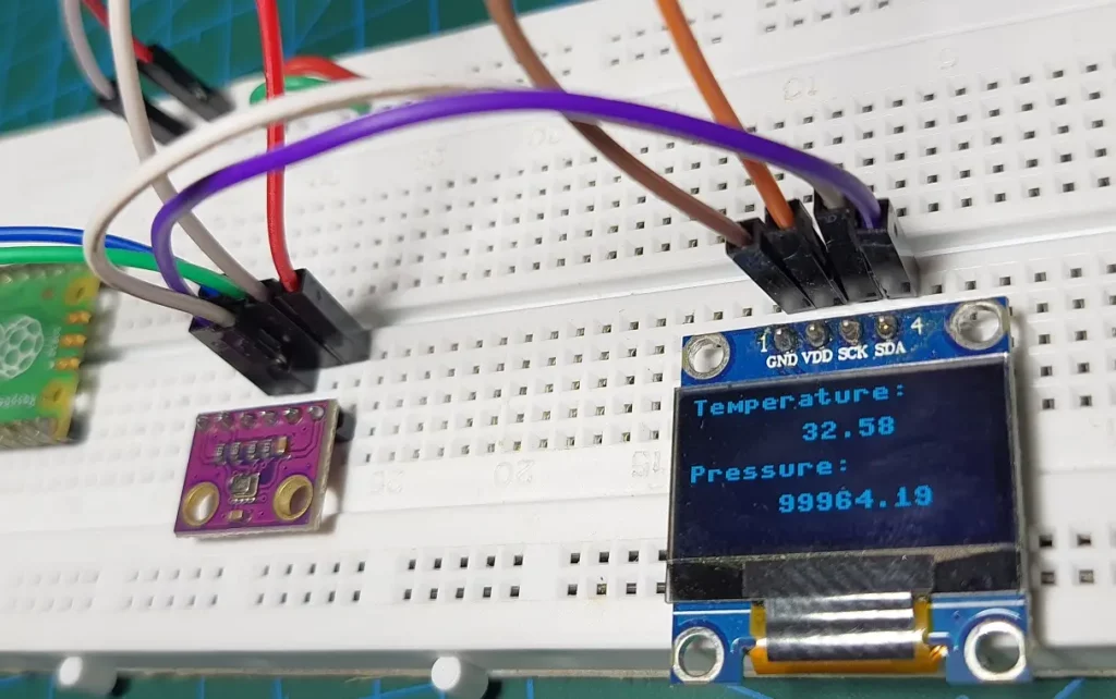
oled.fill(0)Code language: PHP (php)Upon uploading the code, you should see the sensor readings on the OLED module as demonstrated in the image below:
Summary
In this tutorial, we explained how we can use MicroPython code for I2C communication. Examples were shown using ESP32 and Raspberry Pi Pico development boards. We learned how to interface BME280, BMP280, and OLED display modules using MicroPython code. Finally, we saw how we can easily interface multiple I2C devices using a single bus.
Here are links to some of our other articles that use I2C:
Leave a Reply