This tutorial will guide you to interface the DS3231 RTC module with an ESP32 development board. MicroPython code is used to interface the RTC and interfacing an LCD to make a simple digital clock is also explained.
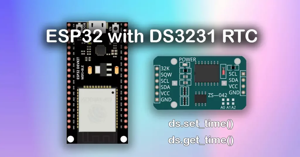
A real-time clock (RTC) is a dedicated integrated circuit used to measure time. These circuits consume very low power and can be powered using batteries such as coin cells. DS3231 is a popular RTC IC and is commonly available as a module (ZS-042) with onboard EEPROM and a battery holder. This ZS-042 module will be used in this guide.
Overview of DS3231 RTC Module
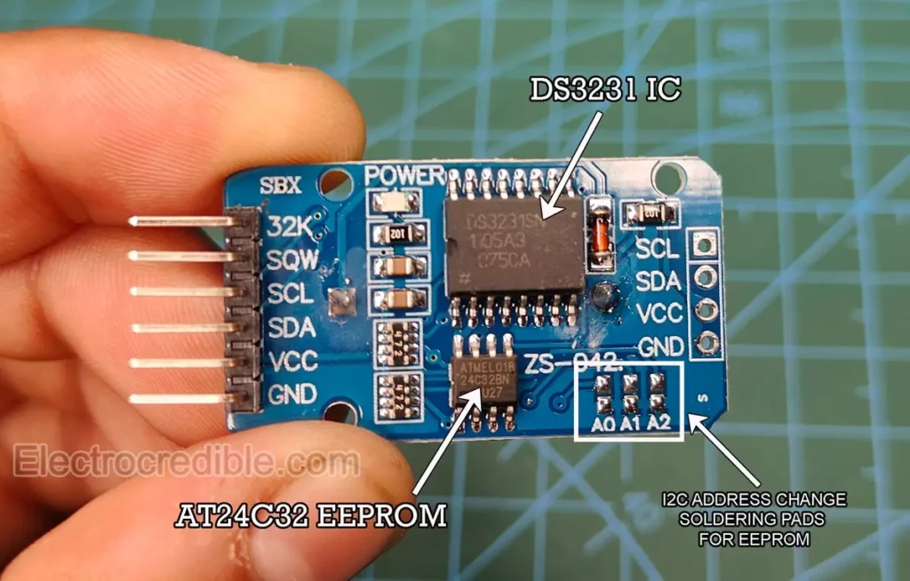
The DS3231 (ZS-042) module features the DS3231 IC and an AT24C32 EEPROM. Both of these ICs can communicate via I2C. The EEPROM is not related to RTC functions but can act as a non-volatile memory for data logging. Onboard soldering pads help to change the address of the EEPROM IC, in case we want to use multiple EEPROM on the same I2C bus. There is a button cell holder on the other side. This module is an all-in-one solution to build data loggers by interfacing with a microcontroller.
Specifications of the DS3231 Module
- Operating Voltage: 2.3 to 5.5V.
- Battery backup: 2.3 to 5.5V. A 3V coin cell is commonly used (such as the CR2032 battery).
- Maximum active supply current: 300 µA.
- Real-time clock counts seconds, minutes, hours, date of the month, month, day of the week, and year, with leap-year compensation valid up to the year 2100.
- Accuracy: ±2ppm from 0°C to +40°C, ±3.5ppm from -40°C to +85°C.
- Fast (400kHz) I2C Interface.
- It is driven by a 32kHz temperature-compensated crystal oscillator (TCXO). The TCXO helps to maintain the RTC within ±2 minutes per year accuracy from -40°C to +85°C.
ⓘ DS1302 is a similar IC that comes at a lower cost than DS3231 but has some shortcomings such as lower accuracy, absence of I2C, and no built-in temperature compensation. You can read about it in our article – Interfacing Raspberry Pi Pico with DS1302.
Powering the Module
The DS32321 RTC module contains a coil cell holder for a rechargeable battery. If we want to power the module using an external supply and non-rechargeable battery (e.g. CR2032) we must do one of the following:
- Remove the battery from the holder while external power is fed through the VCC pin.
- Remove or desolder the onboard resistor near the diode(shown in red). The resistor and diode are used for charging a Lithium-ion coin cell(LIR2032).
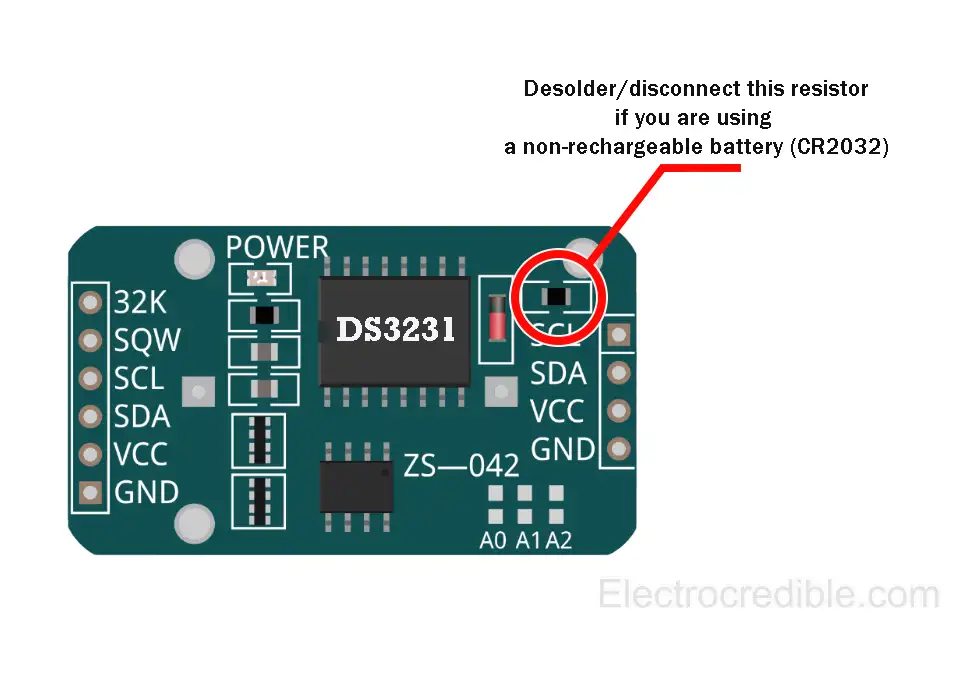
⚠ Using a non-rechargeable battery without following one of these steps may damage your battery.
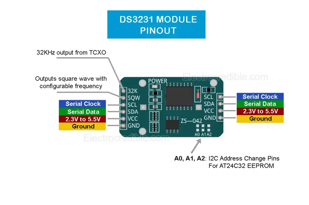
DS3231 Pinout
The DS3231 module provides I2C pins on both sides of the module, which will be convenient in case we want to daisy-chain other I2C devices to the same bus. Below is the pinout of the ZSS-042 DS3231 Module:
Detailed pin description:
| DS3231 Module (ZS-042) Pins | Pin Description |
| 32K | Output a 32KHz wave from the internal TCXO |
| SQW | Square wave output with configurable frequency between 1Hz to 8.192kHz. |
| SCL | Serial Clock pin for I2C interface |
| SDA | Serial Data pin for I2C interface |
| VCC | 2.3V to 5.5V supply voltage |
| GND | Ground pin |
RTC DS3231 with ESP32: Interface Using MicroPython
To run MicroPython code on ESP32, first, we should flash ESP32 with MicroPython firmware. Read the following guides to flash and run MicroPython on ESP32:
- Getting started with MicroPython on ESP32 using Thonny IDE.
- Flash and run MicroPython on ESP32 using uPyCraft IDE.
Circuit Diagram: ESP32 with DS3231 RTC Module
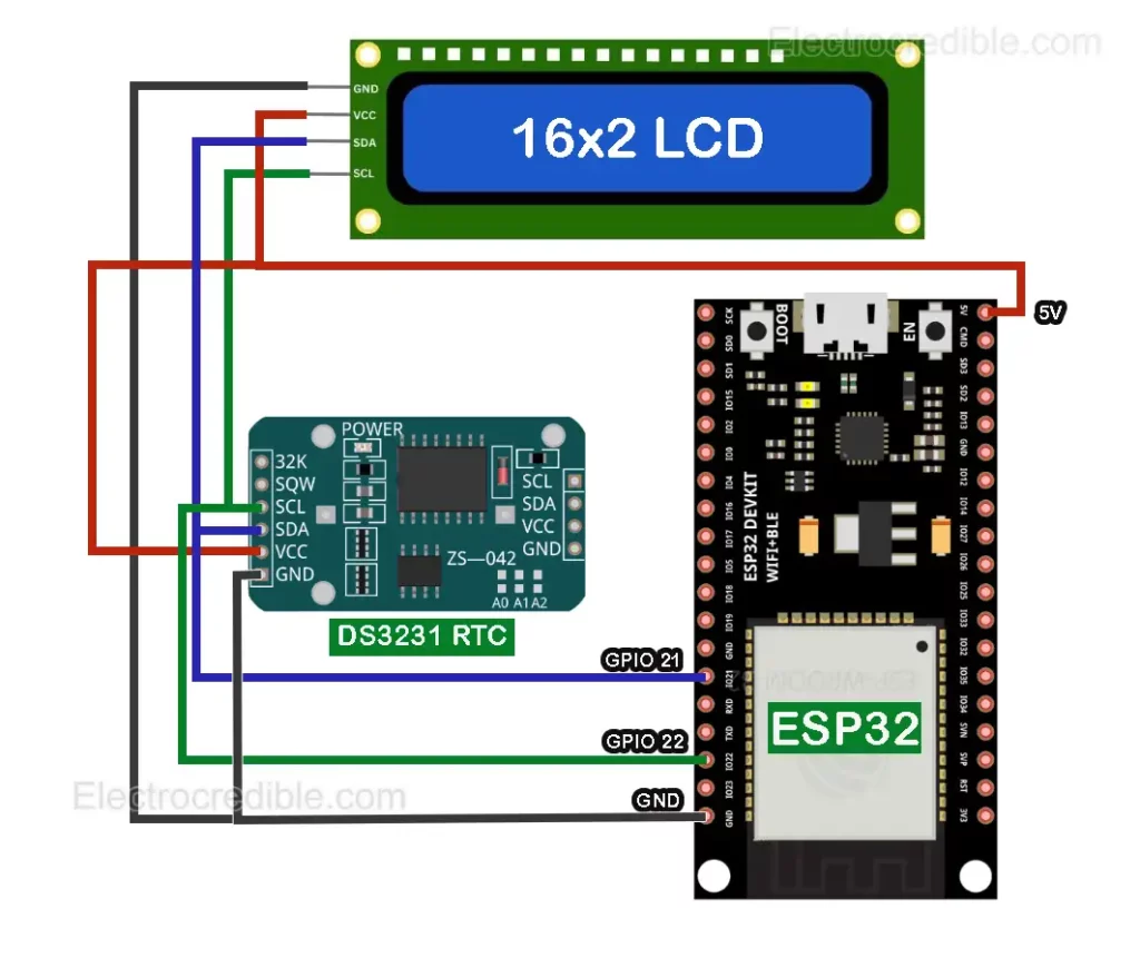
Connect ESP32 with the DS3231 module(ZS-042) as shown in the schematic below.
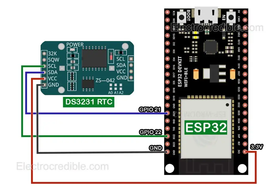
Connection details:
- Connect GPIO 21 of ESP32 to the SDA pin of the DS3231 module.
- Connect GPIO 22 of ESP32 to the SCL pin of the DS3231 module.
- Connect the 3.3V output pin of ESP32 to the VCC pin of DS3231 (the VCC pin requires 2.3V to 5.5V).
- Connect any of the GND (ground) pins of ESP32 to the GND pin of DS3231.
The 32K pin and SQW pin in DS3231 which outputs square wave are not required for interfacing.
After wiring, you can scan for I2C devices and see if DS3231 is detected.
MicroPython Library for DS3231
DS3231 requires various commands to read and retrieve data from the EEPROM, read/write the alarm registers, and other functional registers. Thankfully, various libraries help to easily interface it with microcontrollers.
Here, we shall use the DS3231 MicroPython library by Peter Hinch. The library has methods for DateTime and alarm.
Copy and paste the following DS3231 MicroPython library code and save it to ESP32 as ds3231.py.
# ds3231_gen.py General purpose driver for DS3231 precison real time clock.

# Author: Peter Hinch
# Copyright Peter Hinch 2023 Released under the MIT license.

# Rewritten from datasheet to support alarms. Sources studied:
# WiPy driver at https://github.com/scudderfish/uDS3231
# https://github.com/notUnique/DS3231micro

# Assumes date > Y2K and 24 hour clock.

import time
import machine


_ADDR = const(104)

EVERY_SECOND = 0x0F  # Exported flags
EVERY_MINUTE = 0x0E
EVERY_HOUR = 0x0C
EVERY_DAY = 0x80
EVERY_WEEK = 0x40
EVERY_MONTH = 0

try:
    rtc = machine.RTC()
except:
    print("Warning: machine module does not support the RTC.")
    rtc = None


class Alarm:
    def __init__(self, device, n):
        self._device = device
        self._i2c = device.ds3231
        self.alno = n  # Alarm no.
        self.offs = 7 if self.alno == 1 else 0x0B  # Offset into address map
        self.mask = 0

    def _reg(self, offs : int, buf = bytearray(1)) -> int:  # Read a register
        self._i2c.readfrom_mem_into(_ADDR, offs, buf)
        return buf[0]

    def enable(self, run):
        flags = self._reg(0x0E) | 4  # Disable square wave
        flags = (flags | self.alno) if run else (flags & ~self.alno & 0xFF)
        self._i2c.writeto_mem(_ADDR, 0x0E, flags.to_bytes(1, "little"))

    def __call__(self):  # Return True if alarm is set
        return bool(self._reg(0x0F) & self.alno)

    def clear(self):
        flags = (self._reg(0x0F) & ~self.alno) & 0xFF
        self._i2c.writeto_mem(_ADDR, 0x0F, flags.to_bytes(1, "little"))

    def set(self, when, day=0, hr=0, min=0, sec=0):
        if when not in (0x0F, 0x0E, 0x0C, 0x80, 0x40, 0):
            raise ValueError("Invalid alarm specifier.")
        self.mask = when
        if when == EVERY_WEEK:
            day += 1  # Setting a day of week
        self._device.set_time((0, 0, day, hr, min, sec, 0, 0), self)
        self.enable(True)


class DS3231:
    def __init__(self, i2c):
        self.ds3231 = i2c
        self.alarm1 = Alarm(self, 1)
        self.alarm2 = Alarm(self, 2)
        if _ADDR not in self.ds3231.scan():
            raise RuntimeError(f"DS3231 not found on I2C bus at {_ADDR}")

    def get_time(self, data=bytearray(7)):
        def bcd2dec(bcd):  # Strip MSB
            return ((bcd & 0x70) >> 4) * 10 + (bcd & 0x0F)

        self.ds3231.readfrom_mem_into(_ADDR, 0, data)
        ss, mm, hh, wday, DD, MM, YY = [bcd2dec(x) for x in data]
        YY += 2000
        # Time from DS3231 in time.localtime() format (less yday)
        result = YY, MM, DD, hh, mm, ss, wday - 1, 0
        return result

    # Output time or alarm data to device
    # args: tt A datetime tuple. If absent uses localtime.
    # alarm: An Alarm instance or None if setting time
    def set_time(self, tt=None, alarm=None):
        # Given BCD value return a binary byte. Modifier:
        # Set MSB if any of bit(1..4) or bit 7 set, set b6 if mod[6]
        def gbyte(dec, mod=0):
            tens, units = divmod(dec, 10)
            n = (tens << 4) + units
            n |= 0x80 if mod & 0x0F else mod & 0xC0
            return n.to_bytes(1, "little")

        YY, MM, mday, hh, mm, ss, wday, yday = time.localtime() if tt is None else tt
        mask = 0 if alarm is None else alarm.mask
        offs = 0 if alarm is None else alarm.offs
        if alarm is None or alarm.alno == 1:  # Has a seconds register
            self.ds3231.writeto_mem(_ADDR, offs, gbyte(ss, mask & 1))
            offs += 1
        self.ds3231.writeto_mem(_ADDR, offs, gbyte(mm, mask & 2))
        offs += 1
        self.ds3231.writeto_mem(_ADDR, offs, gbyte(hh, mask & 4))  # Sets to 24hr mode
        offs += 1
        if alarm is not None:  # Setting an alarm - mask holds MS 2 bits
            self.ds3231.writeto_mem(_ADDR, offs, gbyte(mday, mask))
        else:  # Setting time
            self.ds3231.writeto_mem(_ADDR, offs, gbyte(wday + 1))  # 1 == Monday, 7 == Sunday
            offs += 1
            self.ds3231.writeto_mem(_ADDR, offs, gbyte(mday))  # Day of month
            offs += 1
            self.ds3231.writeto_mem(_ADDR, offs, gbyte(MM, 0x80))  # Century bit (>Y2K)
            offs += 1
            self.ds3231.writeto_mem(_ADDR, offs, gbyte(YY - 2000))

    def temperature(self):
        def twos_complement(input_value: int, num_bits: int) -> int:
            mask = 2 ** (num_bits - 1)
            return -(input_value & mask) + (input_value & ~mask)

        t = self.ds3231.readfrom_mem(_ADDR, 0x11, 2)
        i = t[0] << 8 | t[1]
        return twos_complement(i >> 6, 10) * 0.25

    def __str__(self, buf=bytearray(0x13)):  # Debug dump of device registers
        self.ds3231.readfrom_mem_into(_ADDR, 0, buf)
        s = ""
        for n, v in enumerate(buf):
            s = f"{s}0x{n:02x} 0x{v:02x} {v >> 4:04b} {v & 0xF :04b}\n"
            if not (n + 1) % 4:
                s = f"{s}\n"
        return s
MicroPython Code for DS3231
Let us first save the DateTime to the RTC. The code below will set the RTC to the system time using the method ds.set_time(). DateTime tuples are used to set and read time values. These tuples are of the form: (year, month, day, hour, minute, second, weekday, yearday).
# Import necessary modules
from machine import I2C, Pin
from ds3231 import *
import time

# Define the pins for I2C communication
sda_pin=Pin(21)
scl_pin=Pin(22)

# Initialize the I2C interface with the specified pins
i2c = I2C(0, scl=scl_pin, sda=sda_pin)
time.sleep(0.5)

# Create an instance of the DS3231 class for interfacing with the DS3231 RTC
ds = DS3231(i2c)

# Set the DS3231 RTC to current system time
ds.set_time()Code language: PHP (php)
After DateTime is updated, we can print it on the shell using the following script:
from machine import I2C, Pin
from ds3231 import *
import time

sda_pin=Pin(4)
scl_pin=Pin(5)

i2c = I2C(0, scl=scl_pin, sda=sda_pin)
time.sleep(0.5)

ds = DS3231(i2c)

# Print the current date in the format: month/day/year
print( "Date={}/{}/{}" .format(ds.get_time()[1], ds.get_time()[2],ds.get_time()[0]) )

# Print the current time in the format: hours:minutes:seconds
print( "Time={}:{}:{}" .format(ds.get_time()[3], ds.get_time()[4],ds.get_time()[5]) )Code language: PHP (php)
Related: MicroPython Timers Tutorial – ESP32, RPi Pico W, ESP8266 Examples
Steps to Upload MicroPython Code to ESP32
The following steps to upload MicroPython code to ESP32 are explained using Thonny IDE.
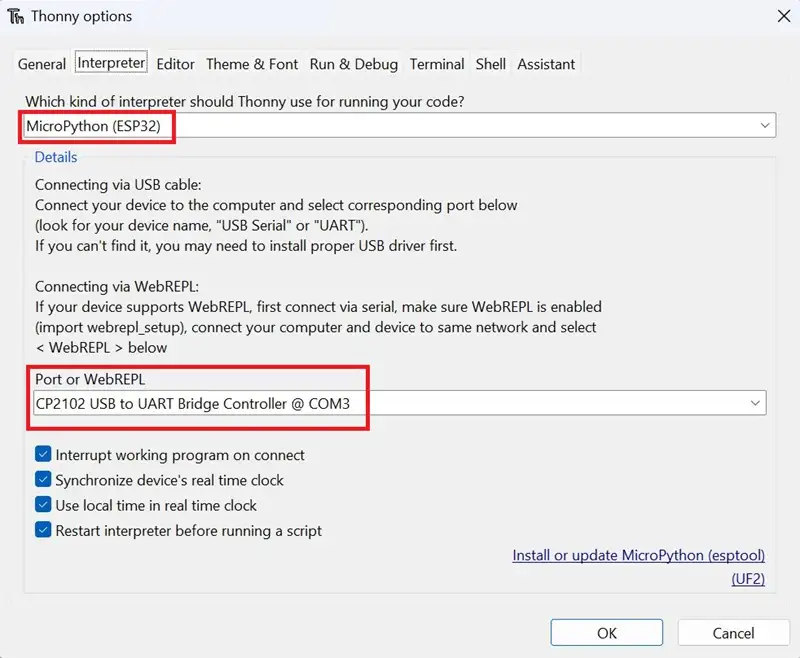
1. In Thonny IDE, set the interpreter to MicroPython on ESP32.
2. Go to File>New in Thonny IDE to create a new project.
3. Paste the code into the new project.
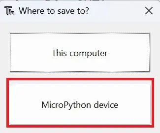
4. Click on File>Save as and select the save location as ‘MicroPython device.’
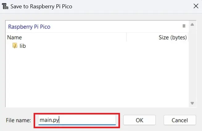
5. Name the main code file main.py or any other file name as required.
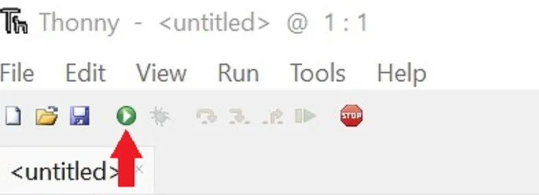
6. Run the code by clicking the Run icon or by pressing the F5 key.
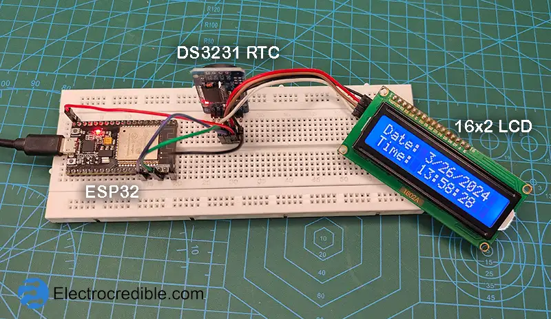
Demonstration
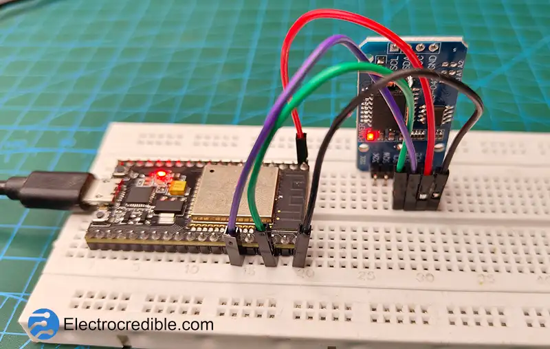
Here is the circuit assembled on a breadboard that consists of the DS3231 module and ESP-WROOM-32 dev board connected with jumper wires.
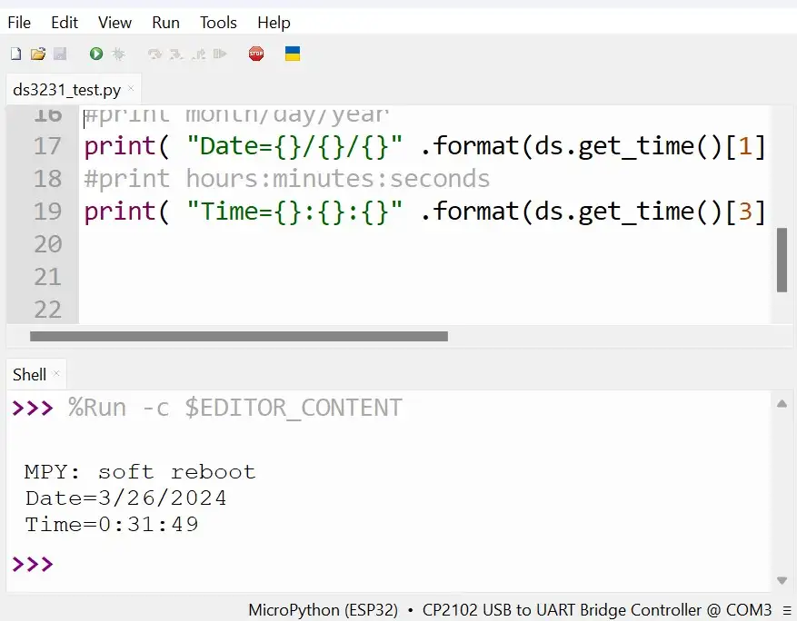
Upon running the code, we can view the output in the shell of Thonny IDE as shown below:
DS3231 Clock: Interface an LCD
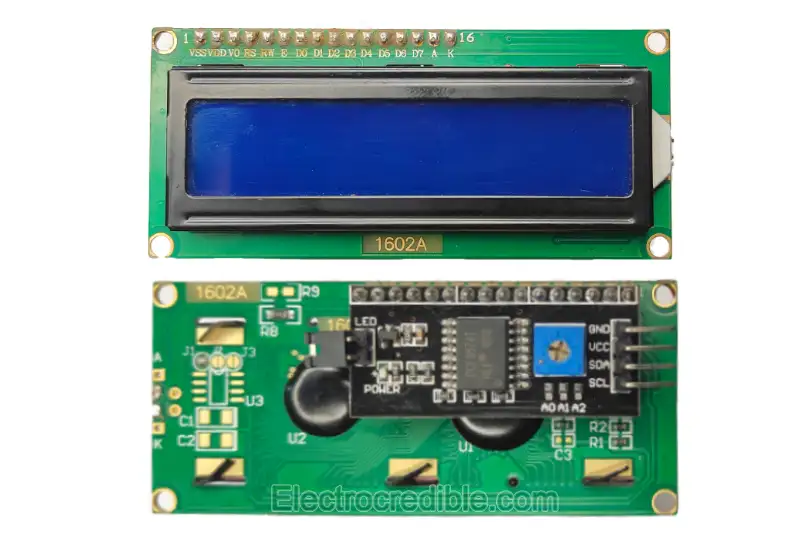
We can easily build a digital clock using DS3231 and a few lines of MicroPython code. Let us see how to interface a 16×2 LCD using the same I2C bus. The LCD has an onboard PCF8574 IC that helps to translate the I2C commands for the LCD controller.
Circuit Diagram of DS3231 with LCD
Connect the components as shown below. The GPIO 21 in ESP32 is used for the SDA line, and GPIO 22 is used for SCL, similar to the connections we made earlier. But this time, the power is derived from the 5V pin of ESP32 as the LCD requires 5V for reliable operation.
Although the ESP32 GPIO pins are rated for 3.3V, communicating via I2C at 5V is not an issue for the ESP32 as the current stays fairly low. However, for a more reliable and safe circuit, use a bidirectional logic level converter between the ESP32 and LCD module.
MicroPython Library for 16×2 LCD
To communicate with the I2C LCD, we shall be using two MicroPython modules.
1. Upload the following code to ESP32 and save it as lcd_api.py.
import time

class LcdApi:

    # Implements the API for talking with HD44780 compatible character LCDs.
    # This class only knows what commands to send to the LCD, and not how to get
    # them to the LCD.
    #
    # It is expected that a derived class will implement the hal_xxx functions.
    #
    # The following constant names were lifted from the avrlib lcd.h header file,
    # with bit numbers changed to bit masks.

    # HD44780 LCD controller command set
    LCD_CLR             = 0x01  # DB0: clear display
    LCD_HOME            = 0x02  # DB1: return to home position

    LCD_ENTRY_MODE      = 0x04  # DB2: set entry mode
    LCD_ENTRY_INC       = 0x02  # DB1: increment
    LCD_ENTRY_SHIFT     = 0x01  # DB0: shift

    LCD_ON_CTRL         = 0x08  # DB3: turn lcd/cursor on
    LCD_ON_DISPLAY      = 0x04  # DB2: turn display on
    LCD_ON_CURSOR       = 0x02  # DB1: turn cursor on
    LCD_ON_BLINK        = 0x01  # DB0: blinking cursor

    LCD_MOVE            = 0x10  # DB4: move cursor/display
    LCD_MOVE_DISP       = 0x08  # DB3: move display (0-> move cursor)
    LCD_MOVE_RIGHT      = 0x04  # DB2: move right (0-> left)

    LCD_FUNCTION        = 0x20  # DB5: function set
    LCD_FUNCTION_8BIT   = 0x10  # DB4: set 8BIT mode (0->4BIT mode)
    LCD_FUNCTION_2LINES = 0x08  # DB3: two lines (0->one line)
    LCD_FUNCTION_10DOTS = 0x04  # DB2: 5x10 font (0->5x7 font)
    LCD_FUNCTION_RESET  = 0x30  # See "Initializing by Instruction" section

    LCD_CGRAM           = 0x40  # DB6: set CG RAM address
    LCD_DDRAM           = 0x80  # DB7: set DD RAM address

    LCD_RS_CMD          = 0
    LCD_RS_DATA         = 1

    LCD_RW_WRITE        = 0
    LCD_RW_READ         = 1

    def __init__(self, num_lines, num_columns):
        self.num_lines = num_lines
        if self.num_lines > 4:
            self.num_lines = 4
        self.num_columns = num_columns
        if self.num_columns > 40:
            self.num_columns = 40
        self.cursor_x = 0
        self.cursor_y = 0
        self.implied_newline = False
        self.backlight = True
        self.display_off()
        self.backlight_on()
        self.clear()
        self.hal_write_command(self.LCD_ENTRY_MODE | self.LCD_ENTRY_INC)
        self.hide_cursor()
        self.display_on()

    def clear(self):
        # Clears the LCD display and moves the cursor to the top left corner
        self.hal_write_command(self.LCD_CLR)
        self.hal_write_command(self.LCD_HOME)
        self.cursor_x = 0
        self.cursor_y = 0

    def show_cursor(self):
        # Causes the cursor to be made visible
        self.hal_write_command(self.LCD_ON_CTRL | self.LCD_ON_DISPLAY |
                               self.LCD_ON_CURSOR)

    def hide_cursor(self):
        # Causes the cursor to be hidden
        self.hal_write_command(self.LCD_ON_CTRL | self.LCD_ON_DISPLAY)

    def blink_cursor_on(self):
        # Turns on the cursor, and makes it blink
        self.hal_write_command(self.LCD_ON_CTRL | self.LCD_ON_DISPLAY |
                               self.LCD_ON_CURSOR | self.LCD_ON_BLINK)

    def blink_cursor_off(self):
        # Turns on the cursor, and makes it no blink (i.e. be solid)
        self.hal_write_command(self.LCD_ON_CTRL | self.LCD_ON_DISPLAY |
                               self.LCD_ON_CURSOR)

    def display_on(self):
        # Turns on (i.e. unblanks) the LCD
        self.hal_write_command(self.LCD_ON_CTRL | self.LCD_ON_DISPLAY)

    def display_off(self):
        # Turns off (i.e. blanks) the LCD
        self.hal_write_command(self.LCD_ON_CTRL)

    def backlight_on(self):
        # Turns the backlight on.

        # This isn't really an LCD command, but some modules have backlight
        # controls, so this allows the hal to pass through the command.
        self.backlight = True
        self.hal_backlight_on()

    def backlight_off(self):
        # Turns the backlight off.

        # This isn't really an LCD command, but some modules have backlight
        # controls, so this allows the hal to pass through the command.
        self.backlight = False
        self.hal_backlight_off()

    def move_to(self, cursor_x, cursor_y):
        # Moves the cursor position to the indicated position. The cursor
        # position is zero based (i.e. cursor_x == 0 indicates first column).
        self.cursor_x = cursor_x
        self.cursor_y = cursor_y
        addr = cursor_x & 0x3f
        if cursor_y & 1:
            addr += 0x40    # Lines 1 & 3 add 0x40
        if cursor_y & 2:    # Lines 2 & 3 add number of columns
            addr += self.num_columns
        self.hal_write_command(self.LCD_DDRAM | addr)

    def putchar(self, char):
        # Writes the indicated character to the LCD at the current cursor
        # position, and advances the cursor by one position.
        if char == '\n':
            if self.implied_newline:
                # self.implied_newline means we advanced due to a wraparound,
                # so if we get a newline right after that we ignore it.
                pass
            else:
                self.cursor_x = self.num_columns

        else:
            self.hal_write_data(ord(char))
            self.cursor_x += 1
        if self.cursor_x >= self.num_columns:
            self.cursor_x = 0
            self.cursor_y += 1
            self.implied_newline = (char != '\n')
        if self.cursor_y >= self.num_lines:
            self.cursor_y = 0
        self.move_to(self.cursor_x, self.cursor_y)

    def putstr(self, string):
        # Write the indicated string to the LCD at the current cursor
        # position and advances the cursor position appropriately.
        for char in string:
            self.putchar(char)

    def custom_char(self, location, charmap):
        # Write a character to one of the 8 CGRAM locations, available
        # as chr(0) through chr(7).
        location &= 0x7
        self.hal_write_command(self.LCD_CGRAM | (location << 3))
        self.hal_sleep_us(40)
        for i in range(8):
            self.hal_write_data(charmap[i])
            self.hal_sleep_us(40)
        self.move_to(self.cursor_x, self.cursor_y)

    def hal_backlight_on(self):
        # Allows the hal layer to turn the backlight on.
        # If desired, a derived HAL class will implement this function.
        pass

    def hal_backlight_off(self):
        # Allows the hal layer to turn the backlight off.
        # If desired, a derived HAL class will implement this function.
        pass

    def hal_write_command(self, cmd):
        # Write a command to the LCD.
        # It is expected that a derived HAL class will implement this function.
        raise NotImplementedError

    def hal_write_data(self, data):
        # Write data to the LCD.
        # It is expected that a derived HAL class will implement this function.
        raise NotImplementedError

    def hal_sleep_us(self, usecs):
        # Sleep for some time (given in microseconds)
        time.sleep_us(usecs)
2. Next, upload the following script and save it as i2c_lcd.py to ESP32.
import utime
import gc

from lcd_api import LcdApi
from machine import I2C

# PCF8574 pin definitions
MASK_RS = 0x01       # P0
MASK_RW = 0x02       # P1
MASK_E  = 0x04       # P2

SHIFT_BACKLIGHT = 3  # P3
SHIFT_DATA      = 4  # P4-P7

class I2cLcd(LcdApi):

    #Implements a HD44780 character LCD connected via PCF8574 on I2C

    def __init__(self, i2c, i2c_addr, num_lines, num_columns):
        self.i2c = i2c
        self.i2c_addr = i2c_addr
        self.i2c.writeto(self.i2c_addr, bytes([0]))
        utime.sleep_ms(20)   # Allow LCD time to powerup
        # Send reset 3 times
        self.hal_write_init_nibble(self.LCD_FUNCTION_RESET)
        utime.sleep_ms(5)    # Need to delay at least 4.1 msec
        self.hal_write_init_nibble(self.LCD_FUNCTION_RESET)
        utime.sleep_ms(1)
        self.hal_write_init_nibble(self.LCD_FUNCTION_RESET)
        utime.sleep_ms(1)
        # Put LCD into 4-bit mode
        self.hal_write_init_nibble(self.LCD_FUNCTION)
        utime.sleep_ms(1)
        LcdApi.__init__(self, num_lines, num_columns)
        cmd = self.LCD_FUNCTION
        if num_lines > 1:
            cmd |= self.LCD_FUNCTION_2LINES
        self.hal_write_command(cmd)
        gc.collect()

    def hal_write_init_nibble(self, nibble):
        # Writes an initialization nibble to the LCD.
        # This particular function is only used during initialization.
        byte = ((nibble >> 4) & 0x0f) << SHIFT_DATA
        self.i2c.writeto(self.i2c_addr, bytes([byte | MASK_E]))
        self.i2c.writeto(self.i2c_addr, bytes([byte]))
        gc.collect()

    def hal_backlight_on(self):
        # Allows the hal layer to turn the backlight on
        self.i2c.writeto(self.i2c_addr, bytes([1 << SHIFT_BACKLIGHT]))
        gc.collect()

    def hal_backlight_off(self):
        #Allows the hal layer to turn the backlight off
        self.i2c.writeto(self.i2c_addr, bytes([0]))
        gc.collect()

    def hal_write_command(self, cmd):
        # Write a command to the LCD. Data is latched on the falling edge of E.
        byte = ((self.backlight << SHIFT_BACKLIGHT) |
                (((cmd >> 4) & 0x0f) << SHIFT_DATA))
        self.i2c.writeto(self.i2c_addr, bytes([byte | MASK_E]))
        self.i2c.writeto(self.i2c_addr, bytes([byte]))
        byte = ((self.backlight << SHIFT_BACKLIGHT) |
                ((cmd & 0x0f) << SHIFT_DATA))
        self.i2c.writeto(self.i2c_addr, bytes([byte | MASK_E]))
        self.i2c.writeto(self.i2c_addr, bytes([byte]))
        if cmd <= 3:
            # The home and clear commands require a worst case delay of 4.1 msec
            utime.sleep_ms(5)
        gc.collect()

    def hal_write_data(self, data):
        # Write data to the LCD. Data is latched on the falling edge of E.
        byte = (MASK_RS |
                (self.backlight << SHIFT_BACKLIGHT) |
                (((data >> 4) & 0x0f) << SHIFT_DATA))
        self.i2c.writeto(self.i2c_addr, bytes([byte | MASK_E]))
        self.i2c.writeto(self.i2c_addr, bytes([byte]))
        byte = (MASK_RS |
                (self.backlight << SHIFT_BACKLIGHT) |
                ((data & 0x0f) << SHIFT_DATA))
        self.i2c.writeto(self.i2c_addr, bytes([byte | MASK_E]))
        self.i2c.writeto(self.i2c_addr, bytes([byte]))
        gc.collect()
Note that these files have to be stored in the internal memory of ESP32 along with the library for DS3231.
MicroPython Code
First, set the DateTime in the DS3231 RTC using the code discussed earlier.
Then upload the following code to display the data from DS3231 on the 16×2 LCD:
from machine import I2C, Pin
from ds3231 import *
import time
from lcd_api import LcdApi
from i2c_lcd import I2cLcd

I2C_ADDR     = 0x27
I2C_NUM_ROWS = 2
I2C_NUM_COLS = 16

sda_pin=Pin(21)
scl_pin=Pin(22)

i2c = I2C(0, scl=scl_pin, sda=sda_pin)
ds = DS3231(i2c)

lcd = I2cLcd(i2c, I2C_ADDR, I2C_NUM_ROWS, I2C_NUM_COLS)
time.sleep(0.1)

def disp_time_lcd():
    lcd.clear()
    lcd.move_to(0,0)
    lcd.putstr("Date: {}/{}/{}".format(ds.get_time()[1], ds.get_time()[2],ds.get_time()[0]))
    lcd.move_to(0,1)
    lcd.putstr("Time: {}:{}:{}".format(ds.get_time()[3], ds.get_time()[4],ds.get_time()[5]))

while True:
    disp_time_lcd()
    time.sleep(1)
Code language: JavaScript (javascript)
To understand how the code for the I2C display works, refer to our article: I2C LCD Interfacing Using MicroPython & RPi Pico
Demonstration
Leave a Reply