This article will guide you to use Serial communication in Raspberry Pi Pico using its inbuilt UART(Universal Asynchronous Receiver/Transmitter) and MicroPython. UART is a serial communication peripheral that makes communicating with microcontrollers and ICs easier.
UART is asynchronous, i.e. it does not need a clock signal to establish communication. USART(Universal Synchronous/Asynchronous Receiver/Transmitter) is a similar peripheral that uses an additional clock signal for synchronous communication, and can also function asynchronously.
We will go through the following steps in this guide:
- Upload a MicroPython script to Raspberry Pi Pico to exchange data with an Arduino UNO board.
- Upload a sketch to Arduino UNO to exchange data with Raspberry Pi Pico.
- Toggle LEDs based on Serial data exchanged between Arduino UNO and Pi Pico.
What is Serial Communication?
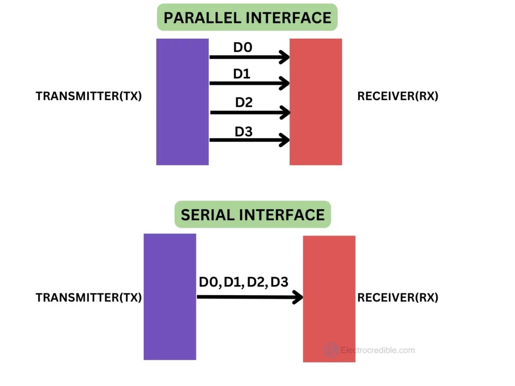
Serial Communication is a method of sending digital data sequentially, bit by bit. Serial communication needs fewer channels(or wires) than parallel communication. In parallel communication, each bit requires its own channel. So 4 bits of data need 4 channels in case of parallel communication but only one channel in Serial communication.
I2C, SPI, and USB are some examples of protocols and interfaces that are used for serial communication. The data lines used for serial communication are collectively termed Serial Bus.
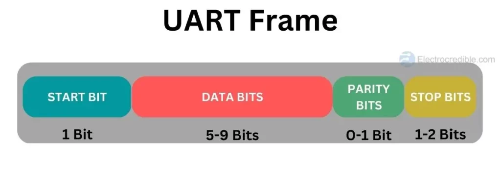
The image above shows a typical UART communication frame. Data is usually sent with the least significant bit first, so the start bit is sent first and the stop bit is sent last. Data bits consist of 5 to 9 bits depending on the coding scheme used. One or two parity bits can be used for detecting errors while communicating.
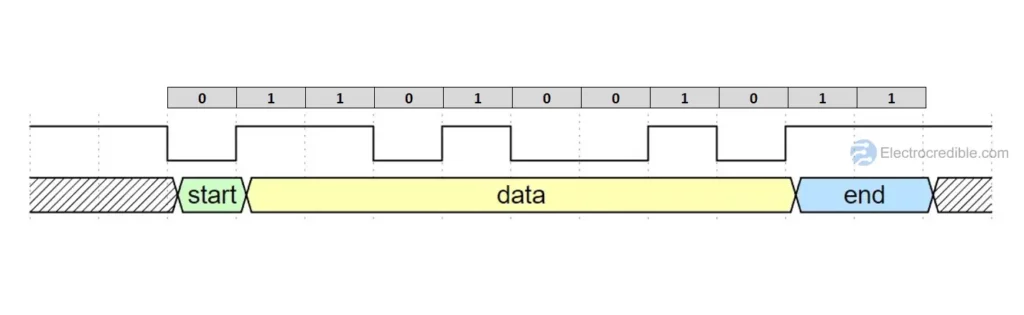
The image above shows an example of the bits in a UART frame which uses 8 data bits, no parity bits, and two stop bits. The signal remains in logical high in an idle state. A low byte signals the start of data reception and two high bits let the receiver know the end of transmission. In the example above the speed of communication is determined by the Baud Rate. Both the sender and receiver need to be set to the same baud rate.
As UART is asynchronous i.e. no common clock signal is used, the receiver relies on its internal clock and the baud rate to interpret the data.
Pinout for Serial Interface in Raspberry Pi Pico
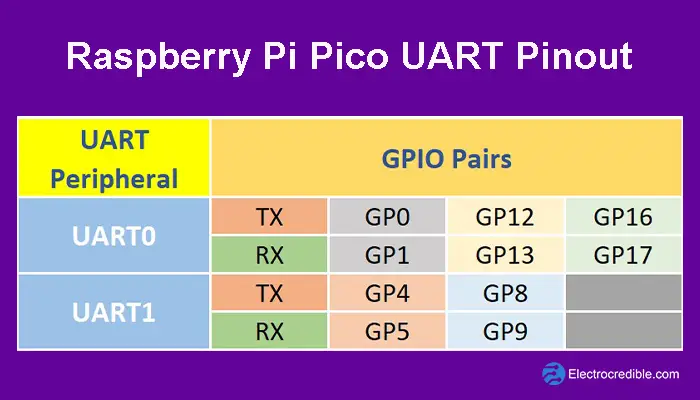
The RP2040 microcontroller in Raspberry Pi Pico has two UART peripherals, UART0 and UART1. The UART in RP2040 has the following features:
- Programmable Baud Rate generator.
- Programmable length of serial data bits(5 to 8 bits) and programmable length of stop bits(1 or 2 stop bits).
- Up to 32 bytes can be stored separately in both transmit and receive modes of the UART, thanks to the inbuilt FIFO memory that buffers the transmit and receive routes.
- Interrupts are triggered based on transmission & reception of data, modem status, communication error, or reception timeout. See section 4.2.6 in the datasheet of RP2040 to know more.
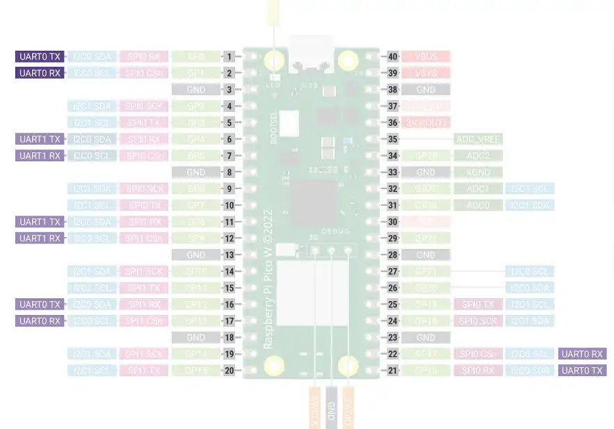
The image below demonstrates the Raspberry Pi Pico pinout which can be used for serial communication via UART.
The UART pins are also highlighted in the Raspberry Pi Pico W Pinout diagram below.
Recommended Article: Raspberry Pi Pico & Pico W Pinout Reference – A Complete Guide.
Prerequisites
- A Raspberry Pi Pico/Pico W.
- Serial terminal software (like PuTTY).
- An Arduino UNO or other Arduino board (optional).
- A bi-directional logic level converter (optional).
- Breadboard and connecting wires (optional).
ⓘ Your Raspberry Pi Pico board needs to be flashed with a MicroPython UF2 file to program it in MicroPython. You can read our getting started guide for Raspberry Pi Pico where we show all steps required to start programming RP2040 in MicroPython.

Raspberry Pi Pico Serial Over USB
The MicroPython REPL is accessed over the USB port of Raspberry Pi Pico/ Pico W. This presents some challenges in establishing bi-directional serial communication over USB. One way of sending and receiving serial data over a USB port is to use the select module in MicroPython.
To demonstrate, I will show a simple script that will toggle the onboard LED in Pico when a serial command(the character ‘t’) is received and will subsequently print the statement “LED toggled” on the shell of IDE.
Upload the following code using your preferred IDE.
import select
import sys
import time
import machine

# Create an instance of a polling object
poll_obj = select.poll()
# Register sys.stdin (standard input) for monitoring read events with priority 1
poll_obj.register(sys.stdin,1)
# Pin object for controlling onboard LED
led=machine.Pin("LED",machine.Pin.OUT)

while True:
    # Check if there is any data available on sys.stdin without blocking
    if poll_obj.poll(0):
        # Read one character from sys.stdin
        ch = sys.stdin.read(1)
        # Check if the character read is 't'
        if ch=='ty':
            # Toggle the state of the LED
            led.value(not led.value())
            # Print a message indicating that the LED has been toggled
            print ("LED toggled" )
    # Small delay to avoid high CPU usage in the loop
    time.sleep(0.1)
Code language: PHP (php)
If you are using Thonny IDE you can follow the steps below to upload MicroPython code.
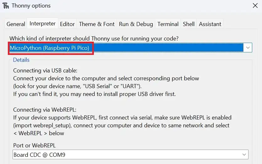
1. Connect the Pico to your computer using a USB cable. Open Thonny IDE and set the interpreter to use MicroPython on Raspberry Pi Pico.
2. Go to File>New in Thonny IDE to create a new project.
3. Paste the code given above.
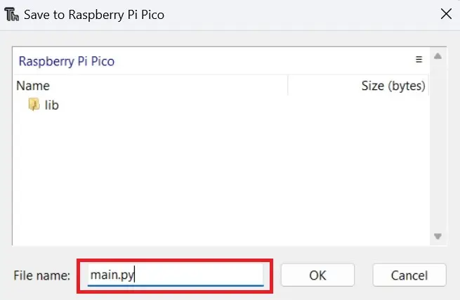
4. Click on File>Save as and select the save location as Raspberry Pi Pico.
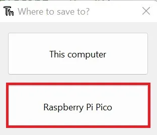
5. Name the code file as main.py.
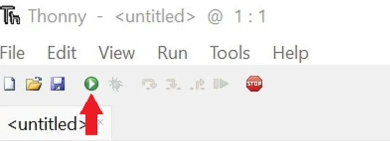
6. Run the code by clicking the Run icon or by pressing the F5 key.
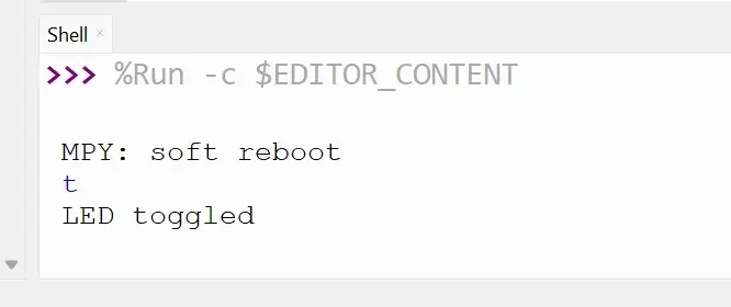
If you type the letter ‘t’ in the shell of Thonny, the LED must change its state from on to off and vice versa. The screenshot below demonstrates the output in Thonny shell after the serial command ‘t’ was sent.
You can read more than 1 character by changing the line of code ch = sys.stdin.read(1). For example, to read three characters from the serial port, change the line to ch = sys.stdin.read(3).
Unlike the slightly complicated way to read serial data, it is easier to write serial data by just using the print() statement.
Using a Serial Terminal Program
To communicate with software other than the IDE, you should close the IDE so that the serial communication with Pico is broken. Either physically disconnect and reconnect the USB cable of Pi Pico, or reset Pi Pico by grounding the RUN pin. This action will free the USB port so that other programs can communicate.
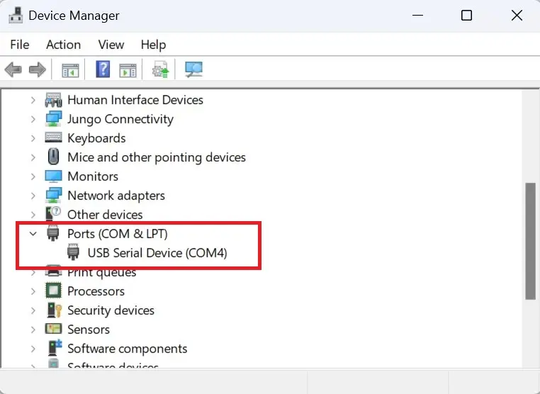
I used PuTTY which is an open-source serial port communication utility. You need to identify the PORT to which your Pico is connected. In Windows, you can go to Device Manager and then select the Ports section, where you will find the PORT number.
Open PuTTY and set the connection type to Serial. Also, set the correct port (PORT4 in my case).
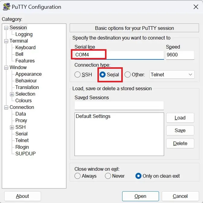
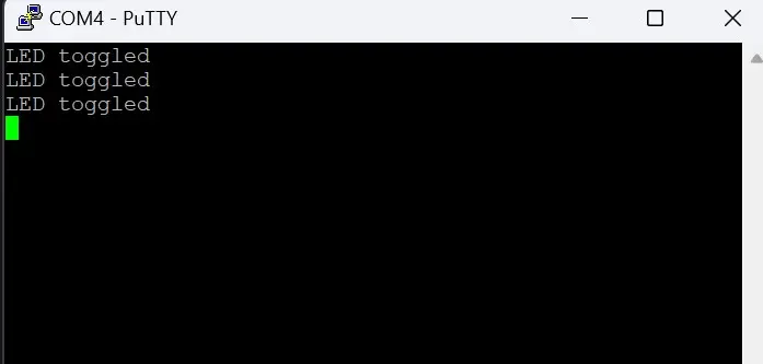
Then click on Open. A new terminal window should appear. Upon typing ‘t’ on the terminal, the onboard LED of Pi Pico changed its state, and a message “LED toggled” was displayed on the terminal.
UART Example: Send Serial Data Between Arduino UNO and Raspberry Pi Pico
Let us write simple code to communicate using serial data between an Arduino UNO and Raspberry Pi Pico W. The code in both the development boards will do the following:
- Raspberry Pi Pico will send a character(char data type) over the serial bus to Arduino UNO.
- Then, the Arduino board will check if a character is received. If it is the expected character, the LED present on the UNO board will change its state(ON to OFF and vice-versa).
- The Arduino board will thereafter send a character to Raspberry Pi Pico over the serial bus.
- Raspberry Pi Pico will toggle its onboard LED if it receives the expected character.
Thus, this simple project will demonstrate how to send and receive data using serial communication in Raspberry Pi Pico. The code for Raspberry Pi Pico is in MicroPython, but you can also use Arduino IDE to code it in C/C++. Read our guide on programming Raspberry Pi Pico using Arduino IDE.
Schematic: Arduino UNO Serial Connection with RPi Pico
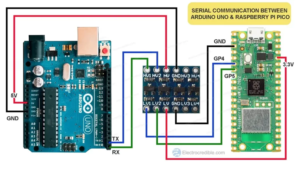
Connect your Pico and Arduino as shown in the diagram above. We are using a bi-directional logic level converter as the Arduino board operates at 5V while RPi Pico operates at 3.3V.
5V input at the Rx pin of Pico can damage the microcontroller. A logic level converter will help convert voltage when sending serial data from Arduino to Raspberry Pi Pico. Read more about how logic level converters work and how to use them in our dedicated article.
You can also use transistors or MOSFETs instead of a logic-level converter module, which is also discussed in the dedicated article.
Also read: Arduino vs MicroPython vs CircuitPython: Which One Will You Choose?
MicroPython Code For Raspberry Pi Pico UART
Your Raspberry Pi Pico needs to be preloaded with a MicroPython UF2 file to program it in MicroPython. You can read our getting started guide for Raspberry Pi Pico where we show all the steps required to start programming Raspberry Pi Pico & Pico W. If you are using macOS, follow our guide to program Raspberry Pi Pico on macOS using Thonny IDE.
First, import the necessary classes, Pin and UART from the machine module. The Pin class assists in interfacing with the GPIOs and the UART class provides functions for serial communication. We also import the time module to introduce delays in code.
from machine import Pin,UART
import timeCode language: JavaScript (javascript)
Create an instance called uart of the UART class and initialize it with UART1 channel, baud rate 9600, TX pin as GPIO4, and RX pin as GPIO5. As we are using UART1, we have to use GPIO4/GPIO8 as the TX pin and GPIOIO5/GP9 as the RX pin.
uart = UART(1, baudrate=9600, tx=Pin(4), rx=Pin(5))Initialize the uart instance with 8 bits of data, no parity bit, and 2 stop bits.
uart.init(bits=8, parity=None, stop=2)Set the pin connected to the onboard LED as an output pin. Create an led object of the Pin class.
led = Pin("LED", Pin.OUT)Code language: JavaScript (javascript)In a while loop, the following sequence of events will occur:
- Send the character ‘t’ via the TX pin of Pico.
- Check if data is available in the RX pin of Pico.
- If data is available, read the data.
- Check if the received data is the character ‘m’. ( This data will be sent from an Arduino board)
- If it is ‘m’, then toggle the LED, then wait for 1 second before repeating the loop.
while True:
    uart.write('t')
    if uart.any():
        data = uart.read()
        if data== b'm':
            led.toggle()
    time.sleep(1)Code language: Python (python)
Full Code
Here is the complete code for the UART interface of Pico. Save it as main.py.
#Source: Electrocredible.com, Language: MicroPython.
from machine import Pin,UART
import time
uart = UART(1, baudrate=9600, tx=Pin(4), rx=Pin(5))
uart.init(bits=8, parity=None, stop=2)
led = Pin("LED", Pin.OUT)

while True:
    uart.write('t')
    if uart.any():
        data = uart.read()
        if data== b'm':
            led.toggle()
    time.sleep(1)Code language: Python (python)
Save the script as main.py.
Code For Arduino Serial Communication
ⓘ NOTE: If you have wired the circuit as shown in the schematic above, disconnect Raspberry Pi Pico from its power-source while uploading code to the Arduino board as it might cause code upload failure. Arduino UNO has a bootloader that relies on serial communication to program the board. Alternatively, you may disconnect the wires connecting the Arduino board and Raspberry Pi Pico.
Open Arduino IDE, paste the following code and upload it to your Arduino board.
bool ledState=1; //variable used to save the state of LED
void setup() {
  Serial.begin(9600);// set baud rate to 9600
  pinMode(LED_BUILTIN, OUTPUT);
}

void loop() {
  if(Serial.read()== 't') {
  digitalWrite(LED_BUILTIN, ledState);
  ledState=!ledState;
  Serial.print('m'); //write 'm' to the UART
  }
}Code language: C++ (cpp)
Result
If the connection was proper and the code was successfully uploaded, the onboard LED of Raspberry Pi Pico and the onboard LED of Arduino UNO must start blinking. The LEDs should stay ON for 1 second and then stay OFF for 1 second.
Also read: Raspberry Pi Pico vs Arduino – Which Board To Choose?
MicroPython Methods for Serial Communication
Using uart as an object, here are some additional MicroPython methods for serial communication:
uart.read(10): read 10 characters, returns a bytes object.uart.readlne(): read a line from UART.uart.readinto(buf): read and store to the given buffer.UART.readinto(buf [, nbytes]): Read up to ‘n‘ bytes into the buffer.uart.write('xyz'): write the three characters ‘xyz‘ to UART.uart.deinit(): disable the UART bus.
For more information, you can visit the MicroPython documentation on UART.
Wrapping Up
You can also view our guide on connecting the HC-05 Bluetooth module with Pico using Serial communication, which will further help you to understand serial communication in Raspberry Pi Pico W.
I hope you found this guide on Raspberry Pi Pico UART using MicroPython to be helpful. Please leave your thoughts in the comments below. Thank you for reading.
Also read: Raspberry Pi Pico I2C Communication Guide With Examples
Leave a Reply