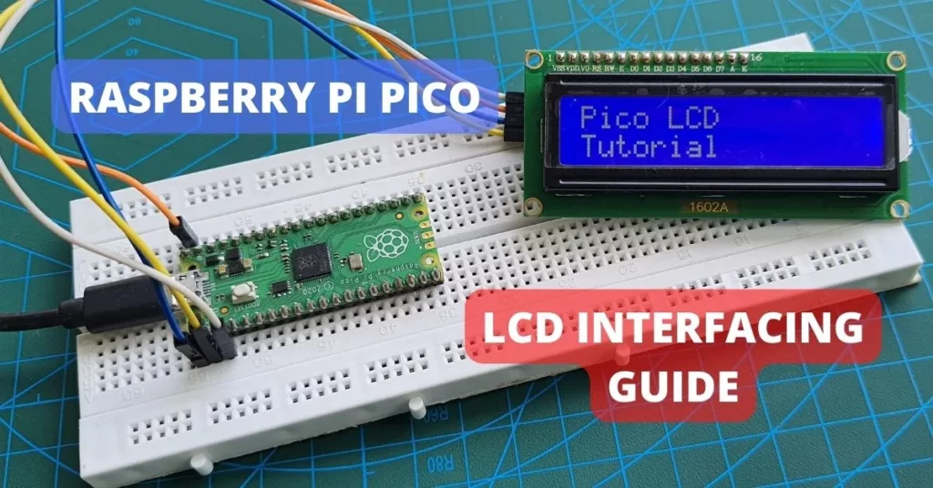
This article will guide you to interface a 16×2 LCD with Raspberry Pi Pico using an I2C interface. MicroPython code is used here to communicate with the LCD. Examples are shown to show sensor data on the LCD using Raspberry Pi Pico.
We will use Thonny IDE to write and upload MicroPython scripts to Raspberry Pi Pico. This tutorial can also be used to interface larger LCDs such as a 20×4 LCD, with minor code changes.
We also have similar tutorials on interfacing other displays with Raspberry Pi Pico:
- Raspberry Pi Pico With OLED Display – MicroPython SSD1306 Example
- NeoPixel WS2812B RGB LED with Raspberry Pi Pico & MicroPython
- Interface 7-Segment Display with Raspberry Pi Pico using MicroPython
- Raspberry Pi Pico W with TM1637 7-Segment Display
Overview of 16×2 I2C LCD Module
By default, 16×2 LCDs come with 16 pins. We need at least 10 pins to communicate with the LCD. To reduce the wire count, there are I2C modules that act as a mediator between the microcontroller and LCD. The advantage is that we need only 4 pins to communicate with the I2C module, which will in turn interface with the 16 pins of the LCD.
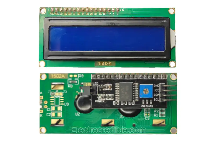
The 16×2 LCD used in this guide has an onboard PCF8574 IC. The PCF8574 is used for I/O expansion and has 8 quasi-bidirectional ports (I/Os). It can communicate with a host microcontroller via I2C and read or write data to its 8 pins, based on the I2C data. For example, we can connect 8 LEDs to the pins of a PCF8574 and control them via the I2C bus.

The A0, A1, and A2 pins that you can see at the bottom of the PCF8574 IC can be connected to either ground or positive voltage to set different addresses for the device. We can connect up to 16 PCF8574 on a single I2C bus, giving us control of 128 I/Os from just two wires of the I2C bus. For more details, you can access the datasheet of PCF8574.
16×2 LCD consists of 16 columns and 2 rows of characters. Each of these characters is made of 5×8 pixels. So in total, we have 5x8x16x2=1280 pixels. Individually controlling these pixels with a microcontroller will be a cumbersome task. So the LCDs come with an attached controller such as HD44780, which takes commands from just a few pins and controls the pixels of the LCDs. The backlight of these LCDs comes in different versions such as blue or green.
Here is the pin description of a 16×2 LCD:
| Pin No. | Symbol | Details |
| 1 | VSS | Supply Ground. |
| 2 | VDD | Supply Positive(5V). |
| 3 | V0 | Contrasts pin connected to a potentiometer. |
| 4 | RS | Register Select. Command mode when pin is set low, and data mode when pin is set high. |
| 5 | RW | Read/Write select pin. |
| 6 | E | Enable. This pin is set high for read-write operations. |
| 7-14 | D0-D7 | Command/Data pins. In 4-wire mode, only pin D4-D7 are required. |
| 15 | A | LED backlight Positive supply. |
| 16 | K | LED backlight negative pin. |
Prerequisites
- Raspberry Pi Pico/ Pico W running MicroPython.
- Breadboard and connecting wires.
- 16×2 LCD.
Your Raspberry Pi Pico needs to be flashed with a MicroPython UF2 file to program it in MicroPython. You can read our getting started guide for Raspberry Pi Pico where we show all the steps required to start programming RP2040 in MicroPython.
If you are using macOS, follow our guide to program Raspberry Pi Pico on macOS using Thonny IDE.
Schematic – Raspberry Pi Pico With LCD
Connect the Raspberry Pi Pico to the LCD as shown in the diagram below. You can use any of the ground pins in the Pico board.

Pin-to-Pin Connection Details:
| Raspberry Pi Pico Pin | I2C LCD Pin |
| GP0 | SDA |
| GP1 | SCL |
| GND | GND |
| VBUS | VCC |
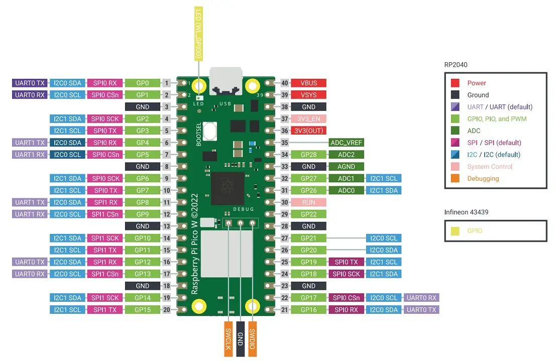
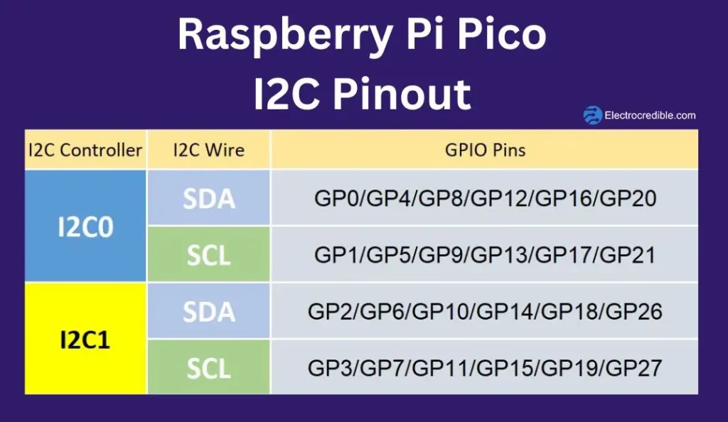
Also, note that RPi Pico W has multiple hardware pins for I2C. We are using GP0 and GP1 in this tutorial, but you can also use other pins with appropriate changes in code. We discuss in-depth the I2C peripheral in Raspberry Pi Pico in our article Raspberry Pi Pico I2C Communication Guide. Below is the pin diagram of Raspberry Pi Pico and details of I2C pins for reference.

Installation of LCD MicroPython Library
To interface the 16×2 LCD with Raspberry Pi Pico W, we will use a MicroPython library by a GitHub user with the pseudonym ‘T-622’. This module is built upon the work of another Github user ‘dhylands’.
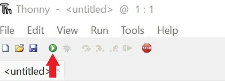
The steps below are demonstrated for Thonny IDE. You can also use the uPyCraft IDE or any other IDE compatible with MicroPython.
First, let us scan the I2C address of the LCD. Connect your RPi Pico W to your computer. Copy the following code and paste it into a new project in Thonny IDE.
import machine
sdaPIN=machine.Pin(0)
sclPIN=machine.Pin(1)
i2c=machine.I2C(0,sda=sdaPIN, scl=sclPIN, freq=400000)
devices = i2c.scan()
if len(devices) == 0:
 print("No i2c device !")
else:
 print('i2c devices found:',len(devices))
for device in devices:
 print("Hexa address: ",hex(device))Code language: Python (python)
Save the script as i2c_scan.py, and run your script.
The Shell window will output the device address which we shall later use in our code. In my case, the hex address was displayed as 0x27.
Now, we will need two MicroPython modules to interface with the LCD.
Create a new file & paste the following script into Thonny IDE. Save it as lcd_api.py. (GitHub link)
import time

class LcdApi:

    # Implements the API for talking with HD44780 compatible character LCDs.
    # This class only knows what commands to send to the LCD, and not how to get
    # them to the LCD.
    #
    # It is expected that a derived class will implement the hal_xxx functions.
    #
    # The following constant names were lifted from the avrlib lcd.h header file,
    # with bit numbers changed to bit masks.

    # HD44780 LCD controller command set
    LCD_CLR             = 0x01  # DB0: clear display
    LCD_HOME            = 0x02  # DB1: return to home position

    LCD_ENTRY_MODE      = 0x04  # DB2: set entry mode
    LCD_ENTRY_INC       = 0x02  # DB1: increment
    LCD_ENTRY_SHIFT     = 0x01  # DB0: shift

    LCD_ON_CTRL         = 0x08  # DB3: turn lcd/cursor on
    LCD_ON_DISPLAY      = 0x04  # DB2: turn display on
    LCD_ON_CURSOR       = 0x02  # DB1: turn cursor on
    LCD_ON_BLINK        = 0x01  # DB0: blinking cursor

    LCD_MOVE            = 0x10  # DB4: move cursor/display
    LCD_MOVE_DISP       = 0x08  # DB3: move display (0-> move cursor)
    LCD_MOVE_RIGHT      = 0x04  # DB2: move right (0-> left)

    LCD_FUNCTION        = 0x20  # DB5: function set
    LCD_FUNCTION_8BIT   = 0x10  # DB4: set 8BIT mode (0->4BIT mode)
    LCD_FUNCTION_2LINES = 0x08  # DB3: two lines (0->one line)
    LCD_FUNCTION_10DOTS = 0x04  # DB2: 5x10 font (0->5x7 font)
    LCD_FUNCTION_RESET  = 0x30  # See "Initializing by Instruction" section

    LCD_CGRAM           = 0x40  # DB6: set CG RAM address
    LCD_DDRAM           = 0x80  # DB7: set DD RAM address

    LCD_RS_CMD          = 0
    LCD_RS_DATA         = 1

    LCD_RW_WRITE        = 0
    LCD_RW_READ         = 1

    def __init__(self, num_lines, num_columns):
        self.num_lines = num_lines
        if self.num_lines > 4:
            self.num_lines = 4
        self.num_columns = num_columns
        if self.num_columns > 40:
            self.num_columns = 40
        self.cursor_x = 0
        self.cursor_y = 0
        self.implied_newline = False
        self.backlight = True
        self.display_off()
        self.backlight_on()
        self.clear()
        self.hal_write_command(self.LCD_ENTRY_MODE | self.LCD_ENTRY_INC)
        self.hide_cursor()
        self.display_on()

    def clear(self):
        # Clears the LCD display and moves the cursor to the top left corner
        self.hal_write_command(self.LCD_CLR)
        self.hal_write_command(self.LCD_HOME)
        self.cursor_x = 0
        self.cursor_y = 0

    def show_cursor(self):
        # Causes the cursor to be made visible
        self.hal_write_command(self.LCD_ON_CTRL | self.LCD_ON_DISPLAY |
                               self.LCD_ON_CURSOR)

    def hide_cursor(self):
        # Causes the cursor to be hidden
        self.hal_write_command(self.LCD_ON_CTRL | self.LCD_ON_DISPLAY)

    def blink_cursor_on(self):
        # Turns on the cursor, and makes it blink
        self.hal_write_command(self.LCD_ON_CTRL | self.LCD_ON_DISPLAY |
                               self.LCD_ON_CURSOR | self.LCD_ON_BLINK)

    def blink_cursor_off(self):
        # Turns on the cursor, and makes it no blink (i.e. be solid)
        self.hal_write_command(self.LCD_ON_CTRL | self.LCD_ON_DISPLAY |
                               self.LCD_ON_CURSOR)

    def display_on(self):
        # Turns on (i.e. unblanks) the LCD
        self.hal_write_command(self.LCD_ON_CTRL | self.LCD_ON_DISPLAY)

    def display_off(self):
        # Turns off (i.e. blanks) the LCD
        self.hal_write_command(self.LCD_ON_CTRL)

    def backlight_on(self):
        # Turns the backlight on.

        # This isn't really an LCD command, but some modules have backlight
        # controls, so this allows the hal to pass through the command.
        self.backlight = True
        self.hal_backlight_on()

    def backlight_off(self):
        # Turns the backlight off.

        # This isn't really an LCD command, but some modules have backlight
        # controls, so this allows the hal to pass through the command.
        self.backlight = False
        self.hal_backlight_off()

    def move_to(self, cursor_x, cursor_y):
        # Moves the cursor position to the indicated position. The cursor
        # position is zero based (i.e. cursor_x == 0 indicates first column).
        self.cursor_x = cursor_x
        self.cursor_y = cursor_y
        addr = cursor_x & 0x3f
        if cursor_y & 1:
            addr += 0x40    # Lines 1 & 3 add 0x40
        if cursor_y & 2:    # Lines 2 & 3 add number of columns
            addr += self.num_columns
        self.hal_write_command(self.LCD_DDRAM | addr)

    def putchar(self, char):
        # Writes the indicated character to the LCD at the current cursor
        # position, and advances the cursor by one position.
        if char == '\n':
            if self.implied_newline:
                # self.implied_newline means we advanced due to a wraparound,
                # so if we get a newline right after that we ignore it.
                pass
            else:
                self.cursor_x = self.num_columns
        else:
            self.hal_write_data(ord(char))
            self.cursor_x += 1
        if self.cursor_x >= self.num_columns:
            self.cursor_x = 0
            self.cursor_y += 1
            self.implied_newline = (char != '\n')
        if self.cursor_y >= self.num_lines:
            self.cursor_y = 0
        self.move_to(self.cursor_x, self.cursor_y)

    def putstr(self, string):
        # Write the indicated string to the LCD at the current cursor
        # position and advances the cursor position appropriately.
        for char in string:
            self.putchar(char)

    def custom_char(self, location, charmap):
        # Write a character to one of the 8 CGRAM locations, available
        # as chr(0) through chr(7).
        location &= 0x7
        self.hal_write_command(self.LCD_CGRAM | (location << 3))
        self.hal_sleep_us(40)
        for i in range(8):
            self.hal_write_data(charmap[i])
            self.hal_sleep_us(40)
        self.move_to(self.cursor_x, self.cursor_y)

    def hal_backlight_on(self):
        # Allows the hal layer to turn the backlight on.
        # If desired, a derived HAL class will implement this function.
        pass

    def hal_backlight_off(self):
        # Allows the hal layer to turn the backlight off.
        # If desired, a derived HAL class will implement this function.
        pass

    def hal_write_command(self, cmd):
        # Write a command to the LCD.
        # It is expected that a derived HAL class will implement this function.
        raise NotImplementedError

    def hal_write_data(self, data):
        # Write data to the LCD.
        # It is expected that a derived HAL class will implement this function.
        raise NotImplementedError

    def hal_sleep_us(self, usecs):
        # Sleep for some time (given in microseconds)
        time.sleep_us(usecs)
Code language: Python (python)
Next, create another new file, paste the following code, and save it as i2c_lcd.py. (Github link)
import utime
import gc
from lcd_api import LcdApi
from machine import I2C
# PCF8574 pin definitions
MASK_RS = 0x01 # P0
MASK_RW = 0x02 # P1
MASK_E = 0x04 # P2
SHIFT_BACKLIGHT = 3 # P3
SHIFT_DATA = 4 # P4-P7
class I2cLcd(LcdApi):
#Implements a HD44780 character LCD connected via PCF8574 on I2C
def __init__(self, i2c, i2c_addr, num_lines, num_columns):
self.i2c = i2c
self.i2c_addr = i2c_addr
self.i2c.writeto(self.i2c_addr, bytes([0]))
utime.sleep_ms(20) # Allow LCD time to powerup
# Send reset 3 times
self.hal_write_init_nibble(self.LCD_FUNCTION_RESET)
utime.sleep_ms(5) # Need to delay at least 4.1 msec
self.hal_write_init_nibble(self.LCD_FUNCTION_RESET)
utime.sleep_ms(1)
self.hal_write_init_nibble(self.LCD_FUNCTION_RESET)
utime.sleep_ms(1)
# Put LCD into 4-bit mode
self.hal_write_init_nibble(self.LCD_FUNCTION)
utime.sleep_ms(1)
LcdApi.__init__(self, num_lines, num_columns)
cmd = self.LCD_FUNCTION
if num_lines > 1:
cmd |= self.LCD_FUNCTION_2LINES
self.hal_write_command(cmd)
gc.collect()
def hal_write_init_nibble(self, nibble):
# Writes an initialization nibble to the LCD.
# This particular function is only used during initialization.
byte = ((nibble >> 4) & 0x0f) << SHIFT_DATA
self.i2c.writeto(self.i2c_addr, bytes([byte | MASK_E]))
self.i2c.writeto(self.i2c_addr, bytes([byte]))
gc.collect()
def hal_backlight_on(self):
# Allows the hal layer to turn the backlight on
self.i2c.writeto(self.i2c_addr, bytes([1 << SHIFT_BACKLIGHT]))
gc.collect()
def hal_backlight_off(self):
#Allows the hal layer to turn the backlight off
self.i2c.writeto(self.i2c_addr, bytes([0]))
gc.collect()
def hal_write_command(self, cmd):
# Write a command to the LCD. Data is latched on the falling edge of E.
byte = ((self.backlight << SHIFT_BACKLIGHT) |
(((cmd >> 4) & 0x0f) << SHIFT_DATA))
self.i2c.writeto(self.i2c_addr, bytes([byte | MASK_E]))
self.i2c.writeto(self.i2c_addr, bytes([byte]))
byte = ((self.backlight << SHIFT_BACKLIGHT) |
((cmd & 0x0f) << SHIFT_DATA))
self.i2c.writeto(self.i2c_addr, bytes([byte | MASK_E]))
self.i2c.writeto(self.i2c_addr, bytes([byte]))
if cmd <= 3:
# The home and clear commands require a worst case delay of 4.1 msec
utime.sleep_ms(5)
gc.collect()
def hal_write_data(self, data):
# Write data to the LCD. Data is latched on the falling edge of E.
byte = (MASK_RS |
(self.backlight << SHIFT_BACKLIGHT) |
(((data >> 4) & 0x0f) << SHIFT_DATA))
self.i2c.writeto(self.i2c_addr, bytes([byte | MASK_E]))
self.i2c.writeto(self.i2c_addr, bytes([byte]))
byte = (MASK_RS |
(self.backlight << SHIFT_BACKLIGHT) |
((data & 0x0f) << SHIFT_DATA))
self.i2c.writeto(self.i2c_addr, bytes([byte | MASK_E]))
self.i2c.writeto(self.i2c_addr, bytes([byte]))
gc.collect()
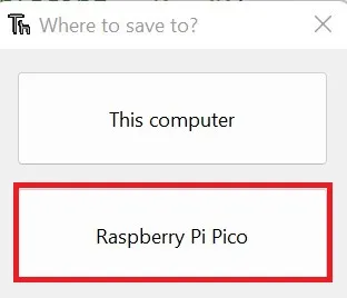
Code language: Python (python)Be careful with the file names as it would otherwise create problems while importing these files into our main program. Store both these files in Raspberry Pi Pico’s Flash memory.
MicroPython Code – Raspberry Pi Pico LCD Interfacing
With the modules installed, we can now write the main script to interface the LCD. Copy the following script to a new file in Thonny.
# Source: Electrocredible.com, Language: MicroPython
import time
from machine import Pin,I2C
from lcd_api import LcdApi
from i2c_lcd import I2cLcd

I2C_ADDR     = 0x27
I2C_NUM_ROWS = 2
I2C_NUM_COLS = 16

i2c = I2C(0, sda=Pin(0), scl=Pin(1), freq=400000)
lcd = I2cLcd(i2c, I2C_ADDR, I2C_NUM_ROWS, I2C_NUM_COLS)
time.sleep(1)
lcd.clear()
lcd.move_to(0,0)
lcd.putstr("Pico LCD")
lcd.move_to(0,1)
lcd.putstr("Tutorial")
Code language: Python (python)
Save this script as main.py. When you run the script, you should now see your LCD working.

If the characters are not displayed on the LCD-
- Adjust the contrast of the LCD by rotating the potentiometer on the back of the LCD module.
- Ensure you are using the correct I2C address. Run the script to scan the I2C address as explained earlier in this article.
- Recheck the connections.
16×2 I2C LCD Interfacing Code Explained
First, we import the required MicroPython libraries. From the machine module, we import the Pin and I2C classes to interact with Pico’s hardware. Then we import the classes from the two LCD driver codes we saved earlier. We also import the utime module for introducing delays in our script.
import utime
from machine import Pin,I2C
from lcd_api import LcdApi
from i2c_lcd import I2cLcdCode language: Python (python)
Remember the I2C address that we scanned earlier? We enter this address(0x27) in our main script and also specify the rows and columns of the LCD that we are using. In our case, it’s a 16×2 display. If you are using another display, then change your code as required. For example, for a 20×4 LCD, modify your code as I2C_NUM_ROWS = 4 and I2C_NUM_COLS = 20.
I2C_ADDR     = 0x27
I2C_NUM_ROWS = 2
I2C_NUM_COLS = 16Code language: Python (python)
We create an I2C object that specifies the SDA and SCL pins we are using on our Pico. The clock frequency is set to 400Khz. Then we create an I2cLcd object specifying the rows, columns, and address.
i2c = I2C(0, sda=Pin(0), scl=Pin(1), freq=400000)
lcd = I2cLcd(i2c, I2C_ADDR, I2C_NUM_ROWS, I2C_NUM_COLS)
The method lcd.clear() clears the display. Now to print text at a certain position in the display, we use lcd.move_to(x,y). This method takes two arguments, the x-position & y-position, from which text should be printed. For example, lcd.moveto(0,1) will start printing text from the first column in the second row. Like indexes in an array, 0 indicates row1 / column 1. So lcd.moveto(0,1) can be interpreted as lcd.moveto(first column, second row). We print two lines of text with the following piece of code.
lcd.move_to(0,0)
lcd.putstr("Pico LCD")
lcd.move_to(0,1)
lcd.putstr("Tutorial")Code language: Python (python)
LCD Example
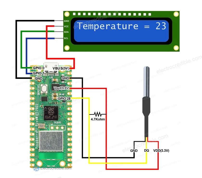
Let us now look at an example of using an LCD to display data from a temperature sensor.
The image below shows the wiring of Raspberry Pi Pico with a DS18B20 temperature sensor and an LCD. DS18B20 is an easy-to-interface temperature sensor that needs only three wires. A pull-up resistor of around 4.7 KΩ is required on the DQ line.
Here is the MicroPython code to display the temperature read by DS18B20 on a 16×2 LCD using I2C:
from machine import Pin, I2C
import time
import onewire
import ds18x20
from lcd_api import LcdApi
from i2c_lcd import I2cLcd

ow = onewire.OneWire(Pin(28))
ds = ds18x20.DS18X20(ow)

devices = ds.scan()
print('found devices:', devices)

I2C_ADDR     = 0x27
I2C_NUM_ROWS = 2
I2C_NUM_COLS = 16

i2c = I2C(0, sda=machine.Pin(0), scl=machine.Pin(1), freq=400000)
lcd = I2cLcd(i2c, I2C_ADDR, I2C_NUM_ROWS, I2C_NUM_COLS)

def getTemp():
    global temp
    ds.convert_temp()
    for device in devices:
        temp=round(ds.read_temp(device))

def dispTemp():
    lcd.clear()
    lcd.move_to(0,0)
    lcd.putstr("Temperature= ")
    lcd.move_to(12,0)
    lcd.putstr(str(temp))

while True:
    getTemp()
    dispTemp()
    time.sleep_ms(750)Code language: JavaScript (javascript)
More details on this example can be found in our article Interfacing Raspberry Pi Pico With DS18B20 Temperature Sensor.
Wrapping Up
I hope this Raspberry Pi Pico LCD interfacing guide was helpful for you. You can easily modify the instructions in this article to display data from different sensors such as the BME280 or BMP280. Please leave your queries and thoughts in the comments below.
Suggested article: MicroPython I2C Guide: Examples Using ESP32 & RPi Pico
Leave a Reply