In this guide, learn how to interface the DS18B20 temperature sensor with Raspberry Pi Pico using MicroPython code. The tutorial will teach you how to wire DS18B20 with RPi Pico and get temperature data from the sensor using MicroPython code.

Overview of DS18B20 Temperature Sensor
The DS18B20 is an easy-to-interface temperature sensor that uses the 1-Wire® protocol, which enables it to communicate using just two wires. Multiple DS18B20s can be connected using a single wire for data transfer. The sensor is available as a TO-92 package and as a waterproof probe which enables its use in wet and high-humidity environments.
DS18B20 Pinout
DS18B20 has three terminals – GROUND, DQ, and VDD. The sensor can be operated in normal mode by providing an external power source at the VDD pin, or in ‘parasitic mode‘ which only requires the DQ and VDD pins. In parasitic mode, the sensor derives power from the DQ line. Below is the pinout diagram of DS18B20.
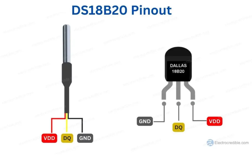
Generally, in DS18B20, the red wire is VDD, the black wire is the Ground, and the yellow wire is connected to the DQ pin.
DS18B20 Features and Specifications
DS18B20 has the following electrical characteristics:
- Supply Voltage(VDD): 3V to 5.5V.
- Standby current: 750nA (typical).
- Active current: 1mA (typical).
- Voltage range on any pin relative to ground: -0.5V to +6.0V
Below are some key features of DS18B20:
- Wide temperature range: The sensor can measure temperature over a wide range, from -55°C to +125°C.
- High accuracy: The DS18B20 can measure temperature with an accuracy of ±0.5°C (between -10°C and +85°C).
- 1-wire interface: With a single wire interface, the sensor makes wiring easier and enables the connection of numerous sensors to a single microcontroller or data logger.
- Multiple resolutions: The DS18B20 has several resolution settings, measuring temperatures with resolutions from 9 bits to 12 bits. The measurement accuracy increases with resolution, while conversion times increase.
- Low power consumption: The sensor uses only 1 µA when in standby mode and 750 µA when converting temperatures.
For more details on the DS18B20 sensor, you can refer to its datasheet.
Components Required
- A Raspberry Pi Pico running MicroPython.
- DS18B20 temperature sensor.
- Breadboard and connecting wires.
Also read: Raspberry Pi Pico DHT22 Interfacing Tutorial – Read Temperature And Humidity Using MicroPython
Schematic of DS18B20 With Raspberry Pi Pico W
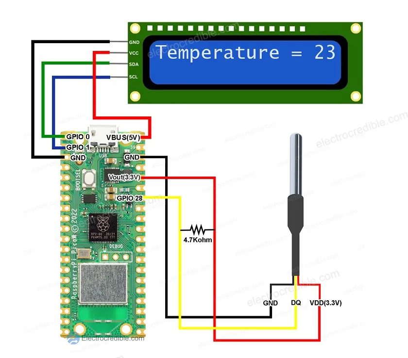
A 4.7K resistor needs to be connected between the DQ pin and VDD pin. The resistor acts as a pull-up for the 1-wire bus. The schematic shown is for the normal mode of DS18B20.
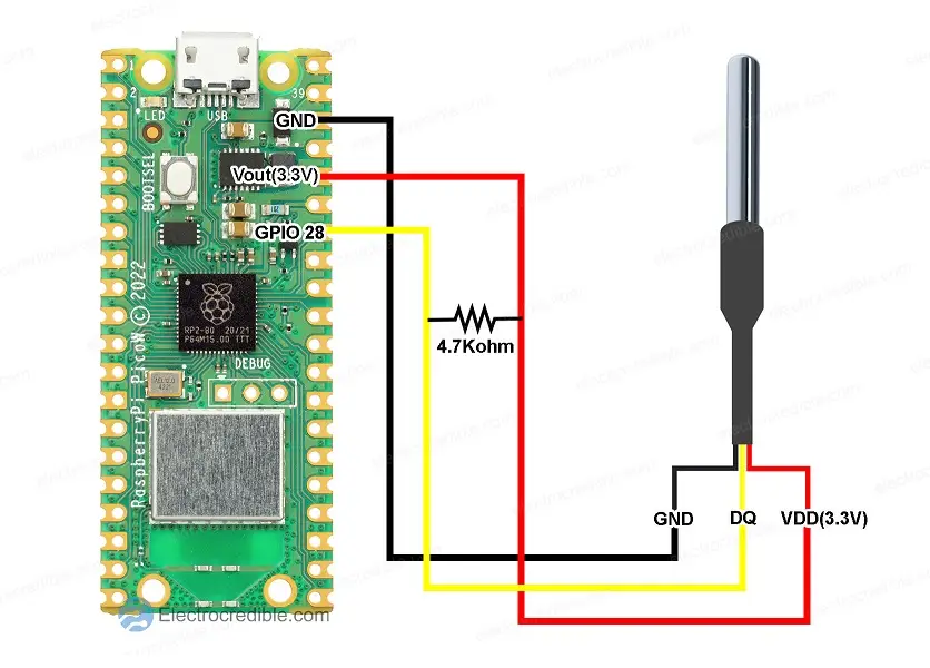
Wiring details
| Raspberry Pi Pico Pin | DS18B20 Pin |
| GND | GND |
| 3V3(OUT) | VDD |
| GPIO28 | DQ |

MicroPython Code Example To Read DS18B20
Before you proceed, your Raspberry Pi Pico needs to be preloaded with a MicroPython UF2 file to program it in MicroPython. You can read our getting started guide for Raspberry Pi Pico where we show all steps required to start programming RP2040 in MicroPython.
We shall discuss programming Pico using the Thonny IDE. You can also use uPyCraft IDE to program Pi Pico.
After you have finished wiring the DS18B20 with Raspberry Pi Pico, you can proceed with the following steps to upload a MicroPython script to your Pico using the Thonny IDE.
- Connect the Pico to your computer using a USB cable. Open Thonny IDE, and paste the following code into a new project.
from machine import Pin
import time
import onewire
import ds18x20

ow = onewire.OneWire(Pin(28))
ds = ds18x20.DS18X20(ow)

devices = ds.scan()
print('found devices:', devices)

while True:
    ds.convert_temp()
    time.sleep_ms(750)
    for device in devices:
        print("Device: {}".format(device))
        print("Temperature= {}".format(ds.read_temp(device)))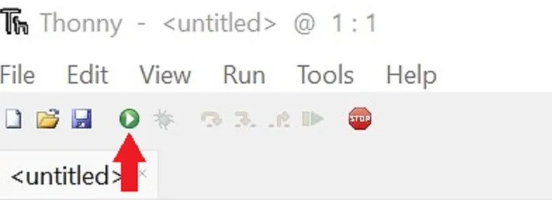
Code language: Python (python)- Run the code by clicking the Run icon or by pressing the F5 key.
- Save the script to your Raspberry Pi Pico.
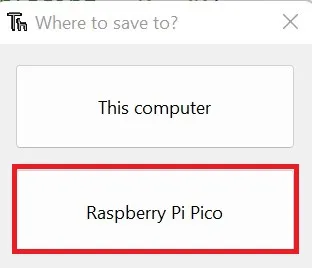
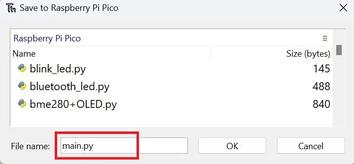
- Save the script as main.py or with any other name with a “.py” filename extension.
You should now see the output in the shell of Thonny IDE as shown below.

Recommended reading: Raspberry Pi Pico Onboard Temperature Sensor Tutorial Using MicroPython
DS18B20 MicroPython Code Explanation
First, we import the necessary modules to interface DS18B20. The Pin class assists in interfacing with the GPIOs, the time module to introduce delays in code. We also import onewire which is a software implementation of 1-wire, and the ds18x20 library which helps to interface DS18S20 and DS18B20 devices.
from machine import Pin
import time
import onewire
import ds18x20Code language: Python (python)
We create an instance ow of the onewire module and specify GPIO28 of Pi Pico for 1-wire communication with DS18B20. Then an instance of the ds18x20 module is also created.
ow = onewire.OneWire(Pin(28))
ds = ds18x20.DS18X20(ow)Code language: Python profile (profile)
Next, we scan for devices connected to the 1-wire bus and save the addresses to the ‘devices‘ variable. The addresses of any connected DS18B20 will be printed. A 64-bit serial code is exclusive to each DS18b20 sensor. This means that many temperature sensors that are connected to the same GPIO can all be read.
devices = ds.scan()
print('found devices:', devices)Code language: Python (python)
Then, in a while loop, we print the temperature every 750ms. Every time we want to sample temperature, we need to call the function ds.convert_temp().
while True:
    ds.convert_temp()
    time.sleep_ms(750)Code language: Python (python)
The datasheet mentions the following conversion times required by DS18B20.
| Resolution | Maximum Temperature Conversion Time |
| 9-bit | 93.75ms |
| 10-bit | 187.5ms |
| 11-bit | 375ms |
| 12-bit | 750ms |
The default resolution of DS18B20 at power-up is 12-bit, so we set a 750ms delay after every temperature sampling.
As we can connect multiple DS18B20 devices to a single 1-wire bus, we print the address of connected devices and their temperature data inside a for loop.
  for device in devices:
        print("Device: {}".format(device))
        print("Temperature= {}".format(ds.read_temp(device)))Code language: Python (python)
Display DS18B20 Temperature On LCD
Let us now try to connect a 16×2 LCD to display the temperature. The LCD uses I2C so interfacing is easy. Connect your RPi Pico, DS18B20, and LCD as shown in the schematic below:
MicroPython Code for DS18B20 With LCD
We need to install two MicroPython modules to interface LCD.
Create a new file and paste the following script and save it as lcd_api.py to your RPi Pico:
import time

class LcdApi:

    # Implements the API for talking with HD44780 compatible character LCDs.
    # This class only knows what commands to send to the LCD, and not how to get
    # them to the LCD.
    #
    # It is expected that a derived class will implement the hal_xxx functions.
    #
    # The following constant names were lifted from the avrlib lcd.h header file,
    # with bit numbers changed to bit masks.

    # HD44780 LCD controller command set
    LCD_CLR             = 0x01  # DB0: clear display
    LCD_HOME            = 0x02  # DB1: return to home position

    LCD_ENTRY_MODE      = 0x04  # DB2: set entry mode
    LCD_ENTRY_INC       = 0x02  # DB1: increment
    LCD_ENTRY_SHIFT     = 0x01  # DB0: shift

    LCD_ON_CTRL         = 0x08  # DB3: turn lcd/cursor on
    LCD_ON_DISPLAY      = 0x04  # DB2: turn display on
    LCD_ON_CURSOR       = 0x02  # DB1: turn cursor on
    LCD_ON_BLINK        = 0x01  # DB0: blinking cursor

    LCD_MOVE            = 0x10  # DB4: move cursor/display
    LCD_MOVE_DISP       = 0x08  # DB3: move display (0-> move cursor)
    LCD_MOVE_RIGHT      = 0x04  # DB2: move right (0-> left)

    LCD_FUNCTION        = 0x20  # DB5: function set
    LCD_FUNCTION_8BIT   = 0x10  # DB4: set 8BIT mode (0->4BIT mode)
    LCD_FUNCTION_2LINES = 0x08  # DB3: two lines (0->one line)
    LCD_FUNCTION_10DOTS = 0x04  # DB2: 5x10 font (0->5x7 font)
    LCD_FUNCTION_RESET  = 0x30  # See "Initializing by Instruction" section

    LCD_CGRAM           = 0x40  # DB6: set CG RAM address
    LCD_DDRAM           = 0x80  # DB7: set DD RAM address

    LCD_RS_CMD          = 0
    LCD_RS_DATA         = 1

    LCD_RW_WRITE        = 0
    LCD_RW_READ         = 1

    def __init__(self, num_lines, num_columns):
        self.num_lines = num_lines
        if self.num_lines > 4:
            self.num_lines = 4
        self.num_columns = num_columns
        if self.num_columns > 40:
            self.num_columns = 40
        self.cursor_x = 0
        self.cursor_y = 0
        self.implied_newline = False
        self.backlight = True
        self.display_off()
        self.backlight_on()
        self.clear()
        self.hal_write_command(self.LCD_ENTRY_MODE | self.LCD_ENTRY_INC)
        self.hide_cursor()
        self.display_on()

    def clear(self):
        # Clears the LCD display and moves the cursor to the top left corner
        self.hal_write_command(self.LCD_CLR)
        self.hal_write_command(self.LCD_HOME)
        self.cursor_x = 0
        self.cursor_y = 0

    def show_cursor(self):
        # Causes the cursor to be made visible
        self.hal_write_command(self.LCD_ON_CTRL | self.LCD_ON_DISPLAY |
                               self.LCD_ON_CURSOR)

    def hide_cursor(self):
        # Causes the cursor to be hidden
        self.hal_write_command(self.LCD_ON_CTRL | self.LCD_ON_DISPLAY)

    def blink_cursor_on(self):
        # Turns on the cursor, and makes it blink
        self.hal_write_command(self.LCD_ON_CTRL | self.LCD_ON_DISPLAY |
                               self.LCD_ON_CURSOR | self.LCD_ON_BLINK)

    def blink_cursor_off(self):
        # Turns on the cursor, and makes it no blink (i.e. be solid)
        self.hal_write_command(self.LCD_ON_CTRL | self.LCD_ON_DISPLAY |
                               self.LCD_ON_CURSOR)

    def display_on(self):
        # Turns on (i.e. unblanks) the LCD
        self.hal_write_command(self.LCD_ON_CTRL | self.LCD_ON_DISPLAY)

    def display_off(self):
        # Turns off (i.e. blanks) the LCD
        self.hal_write_command(self.LCD_ON_CTRL)

    def backlight_on(self):
        # Turns the backlight on.

        # This isn't really an LCD command, but some modules have backlight
        # controls, so this allows the hal to pass through the command.
        self.backlight = True
        self.hal_backlight_on()

    def backlight_off(self):
        # Turns the backlight off.

        # This isn't really an LCD command, but some modules have backlight
        # controls, so this allows the hal to pass through the command.
        self.backlight = False
        self.hal_backlight_off()

    def move_to(self, cursor_x, cursor_y):
        # Moves the cursor position to the indicated position. The cursor
        # position is zero based (i.e. cursor_x == 0 indicates first column).
        self.cursor_x = cursor_x
        self.cursor_y = cursor_y
        addr = cursor_x & 0x3f
        if cursor_y & 1:
            addr += 0x40    # Lines 1 & 3 add 0x40
        if cursor_y & 2:    # Lines 2 & 3 add number of columns
            addr += self.num_columns
        self.hal_write_command(self.LCD_DDRAM | addr)

    def putchar(self, char):
        # Writes the indicated character to the LCD at the current cursor
        # position, and advances the cursor by one position.
        if char == '\n':
            if self.implied_newline:
                # self.implied_newline means we advanced due to a wraparound,
                # so if we get a newline right after that we ignore it.
                pass
            else:
                self.cursor_x = self.num_columns

        else:
            self.hal_write_data(ord(char))
            self.cursor_x += 1
        if self.cursor_x >= self.num_columns:
            self.cursor_x = 0
            self.cursor_y += 1
            self.implied_newline = (char != '\n')
        if self.cursor_y >= self.num_lines:
            self.cursor_y = 0
        self.move_to(self.cursor_x, self.cursor_y)

    def putstr(self, string):
        # Write the indicated string to the LCD at the current cursor
        # position and advances the cursor position appropriately.
        for char in string:
            self.putchar(char)

    def custom_char(self, location, charmap):
        # Write a character to one of the 8 CGRAM locations, available
        # as chr(0) through chr(7).
        location &= 0x7
        self.hal_write_command(self.LCD_CGRAM | (location << 3))
        self.hal_sleep_us(40)
        for i in range(8):
            self.hal_write_data(charmap[i])
            self.hal_sleep_us(40)
        self.move_to(self.cursor_x, self.cursor_y)

    def hal_backlight_on(self):
        # Allows the hal layer to turn the backlight on.
        # If desired, a derived HAL class will implement this function.
        pass

    def hal_backlight_off(self):
        # Allows the hal layer to turn the backlight off.
        # If desired, a derived HAL class will implement this function.
        pass

    def hal_write_command(self, cmd):
        # Write a command to the LCD.
        # It is expected that a derived HAL class will implement this function.
        raise NotImplementedError

    def hal_write_data(self, data):
        # Write data to the LCD.
        # It is expected that a derived HAL class will implement this function.
        raise NotImplementedError

    def hal_sleep_us(self, usecs):
        # Sleep for some time (given in microseconds)
        time.sleep_us(usecs)
Code language: Python (python)
Also save the following code as pico_i2c_lcd.py to your RPi Pico board:
import utime
import gc

from lcd_api import LcdApi
from machine import I2C

# PCF8574 pin definitions
MASK_RS = 0x01       # P0
MASK_RW = 0x02       # P1
MASK_E  = 0x04       # P2

SHIFT_BACKLIGHT = 3  # P3
SHIFT_DATA      = 4  # P4-P7

class I2cLcd(LcdApi):

    #Implements a HD44780 character LCD connected via PCF8574 on I2C

    def __init__(self, i2c, i2c_addr, num_lines, num_columns):
        self.i2c = i2c
        self.i2c_addr = i2c_addr
        self.i2c.writeto(self.i2c_addr, bytes([0]))
        utime.sleep_ms(20)   # Allow LCD time to powerup
        # Send reset 3 times
        self.hal_write_init_nibble(self.LCD_FUNCTION_RESET)
        utime.sleep_ms(5)    # Need to delay at least 4.1 msec
        self.hal_write_init_nibble(self.LCD_FUNCTION_RESET)
        utime.sleep_ms(1)
        self.hal_write_init_nibble(self.LCD_FUNCTION_RESET)
        utime.sleep_ms(1)
        # Put LCD into 4-bit mode
        self.hal_write_init_nibble(self.LCD_FUNCTION)
        utime.sleep_ms(1)
        LcdApi.__init__(self, num_lines, num_columns)
        cmd = self.LCD_FUNCTION
        if num_lines > 1:
            cmd |= self.LCD_FUNCTION_2LINES
        self.hal_write_command(cmd)
        gc.collect()

    def hal_write_init_nibble(self, nibble):
        # Writes an initialization nibble to the LCD.
        # This particular function is only used during initialization.
        byte = ((nibble >> 4) & 0x0f) << SHIFT_DATA
        self.i2c.writeto(self.i2c_addr, bytes([byte | MASK_E]))
        self.i2c.writeto(self.i2c_addr, bytes([byte]))
        gc.collect()

    def hal_backlight_on(self):
        # Allows the hal layer to turn the backlight on
        self.i2c.writeto(self.i2c_addr, bytes([1 << SHIFT_BACKLIGHT]))
        gc.collect()

    def hal_backlight_off(self):
        #Allows the hal layer to turn the backlight off
        self.i2c.writeto(self.i2c_addr, bytes([0]))
        gc.collect()

    def hal_write_command(self, cmd):
        # Write a command to the LCD. Data is latched on the falling edge of E.
        byte = ((self.backlight << SHIFT_BACKLIGHT) |
                (((cmd >> 4) & 0x0f) << SHIFT_DATA))
        self.i2c.writeto(self.i2c_addr, bytes([byte | MASK_E]))
        self.i2c.writeto(self.i2c_addr, bytes([byte]))
        byte = ((self.backlight << SHIFT_BACKLIGHT) |
                ((cmd & 0x0f) << SHIFT_DATA))
        self.i2c.writeto(self.i2c_addr, bytes([byte | MASK_E]))
        self.i2c.writeto(self.i2c_addr, bytes([byte]))
        if cmd <= 3:
            # The home and clear commands require a worst case delay of 4.1 msec
            utime.sleep_ms(5)
        gc.collect()

    def hal_write_data(self, data):
        # Write data to the LCD. Data is latched on the falling edge of E.
        byte = (MASK_RS |
                (self.backlight << SHIFT_BACKLIGHT) |
                (((data >> 4) & 0x0f) << SHIFT_DATA))
        self.i2c.writeto(self.i2c_addr, bytes([byte | MASK_E]))
        self.i2c.writeto(self.i2c_addr, bytes([byte]))
        byte = (MASK_RS |
                (self.backlight << SHIFT_BACKLIGHT) |
                ((data & 0x0f) << SHIFT_DATA))
        self.i2c.writeto(self.i2c_addr, bytes([byte | MASK_E]))
        self.i2c.writeto(self.i2c_addr, bytes([byte]))
        gc.collect()
Finally, you can paste the code below and name it as main.py. The code will display the temperature value in Celcius on the LCD.
from machine import Pin, I2C
import time
import onewire
import ds18x20
from lcd_api import LcdApi
from pico_i2c_lcd import I2cLcd

ow = onewire.OneWire(Pin(28))
ds = ds18x20.DS18X20(ow)

devices = ds.scan()
print('found devices:', devices)

I2C_ADDR     = 0x27
I2C_NUM_ROWS = 2
I2C_NUM_COLS = 16

i2c = I2C(0, sda=machine.Pin(0), scl=machine.Pin(1), freq=400000)
lcd = I2cLcd(i2c, I2C_ADDR, I2C_NUM_ROWS, I2C_NUM_COLS)

def getTemp():
    global temp
    ds.convert_temp()
    for device in devices:
        temp=round(ds.read_temp(device))

def dispTemp():
    lcd.clear()
    lcd.move_to(0,0)
    lcd.putstr("Temperature= ")
    lcd.move_to(12,0)
    lcd.putstr(str(temp))

while True:
    getTemp()
    dispTemp()
    time.sleep_ms(750)
Code language: JavaScript (javascript)
To understand how the additional code works, you can look at our article which describes how to interface an I2C LCD with Raspberry Pi Pico.
Applications Of DS18B20
- Environmental monitoring: Both interior and outdoor temperature monitoring are possible with the DS18B20. Applications for this include managing greenhouses, HVAC systems, and weather monitoring.
- Industrial automation: The DS18B20 can be utilized in industrial automation to track machine and equipment temperature. This can assist to keep the device from overheating and increase its lifespan.
- IoT: To monitor temperature in smart homes, smart buildings, and other connected devices, the DS18B20 can be utilized in IoT applications. Such applications can help to save energy through automation.
Troubleshooting
Have you encountered a code error as shown below?
found devices: []
Traceback (most recent call last):
  File "<stdin>", line 13, in <module>
  File "ds18x20.py", line 1, in convert_temp
  File "onewire.py", line 1, in reset
OneWireError: Code language: JavaScript (javascript)
This can be caused by loose or faulty wiring. Connect DS18B20 properly to Raspberry Pi Pico and try again.
Wrapping Up
You can also make a temperature data logger by following the instructions in our guide to build a sensor data logger using RPi Pico W. With slight modifications, you can log DS18B20 data to flash memory. You can also make this project portable by powering Raspberry Pi Pico with batteries.
Hope you found this guide helpful. Please leave your valuable feedback and queries in the comments below.
Leave a Reply