This article will show various ways to power Raspberry Pi Pico & Pico W with batteries. Both rechargeable and non-rechargeable batteries will be discussed along with charging/discharging circuitry. Powering Raspberry Pi Pico/Pico W with batteries allows you to take your projects with you on the go. Portable power enables you to deploy Raspberry Pi Pico in locations where a stable power source might not be readily available. This is invaluable for applications like environmental monitoring, or data collection in the field through sensor networks.
The following types of batteries will be used to power Pico W in this guide:
- 18650 Lithiuim-ion.
- 9V battery.
- AAA & AA batteries.
- Lead acid batteries (6V, 12V, 24V etc).
If you’re interested in wearable technology, Raspberry Pi Pico powered by batteries can be used to create wearable devices and health trackers. Although a power bank can power RPi Pico with batteries, it may be overkill and costly in some situations. We’ll delve into the various techniques and considerations that enable you to use Raspberry Pi Pico without the USB cable.
How To Power Raspberry Pi Pico Without Using USB Port
Let us understand the onboard pins and the power supply circuit in Raspberry Pi Pico & Pico W. Take a look at the pinout of power-related pins in Raspberry Pi Pico & Pico W marked in red color:
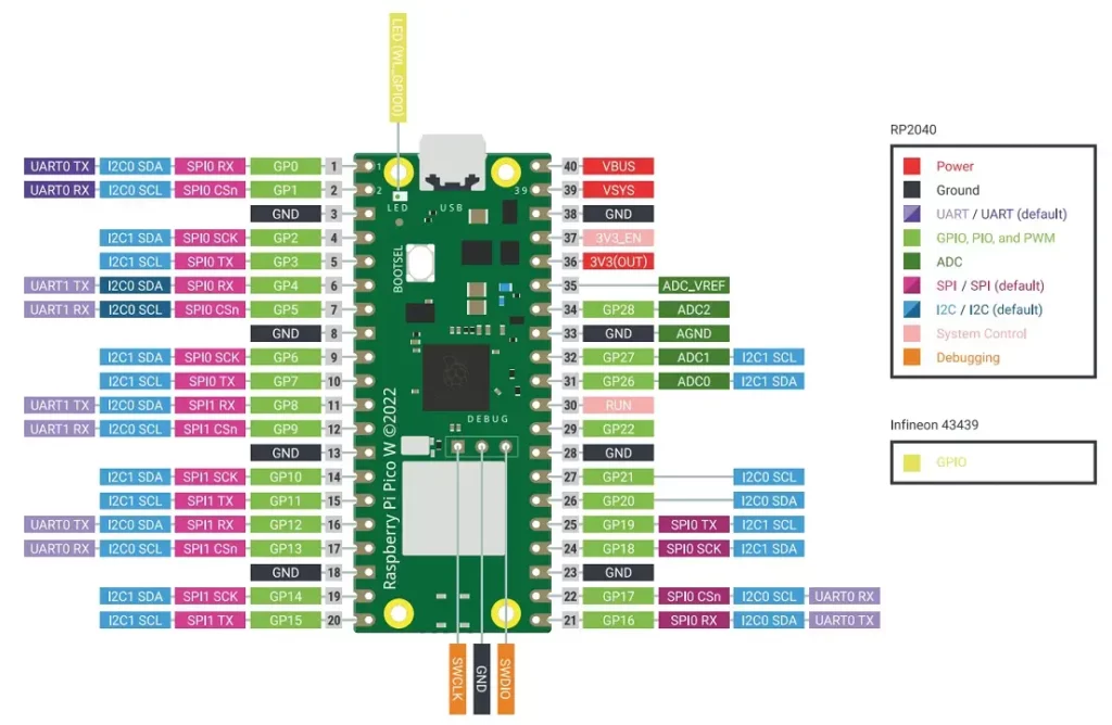
Pin definitions:
- VBUS (PIN 40): This pin is connected to the micro-USB port and allows the Pico W to be powered through. It accepts a voltage range of 4.5V to 5.5V
- VSYS (PIN 39): Pin for main system input voltage. The input voltage can vary between 1.8V to 5.5V. This voltage is used by the onboard SMPS to generate 3.3V to power the RP2040 microcontroller and GPIOs.
- 3V3_EN (PIN 37): Used to enable the onboard SMPS for 3.3V. It is pulled high to the VSYS pin using a 100kΩ resistor.
- 3V3(OUT) (PIN 36): Outputs a regulated 3.3V voltage that can be used to power external components such as sensors. The datasheet recommends keeping the maximum load current from this pin to be under 300mA.
- GND: These pins provide the reference ground for the Pico W and connected devices. There are 8 GND pins available on the edge pinouts of Pico, all serving the same purpose.
- RUN (PIN 30): Enable pin for the RP2040 microcontroller. It is internally pulled up to 3.3V. It can be used to reset the Raspberry Pi Pico.
The VBUS voltage is fed through a Schottky diode to generate VSYS. The datasheet of Raspberry Pi Pico mentions – “If the USB port is not going to be used, it is safe to power Pico by connecting VSYS to your preferred power source (in the range ~1.8V to 5.5V).”
Therefore, you can use a single Li-ion battery (~3.7V) or 2/3 AA batteries in series to power your RPi Pico.
Also read: Raspberry Pi Pico & Pico W Pinout Guide – All Pins Explained
Adding a Diode for Safety
In order to safely connect a battery or secondary power source to Pico, we can add a diode between the second power source and the VSYS pin. This will prevent one power source from back-feeding the other. Whichever power source has the higher voltage will send power to the Raspberry Pi Pico board.
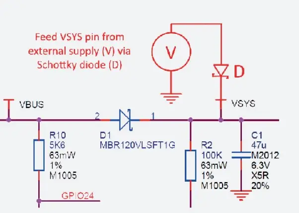
The D1 diode in the image above shows a Schottky diode connected between VBUS and VSYS pins of RPi Pico. Schottky diode is selected because it has a lower forward voltage drop than other diodes.
Instead of a Schottky diode, a commonly available rectifier diode such as the 1N4007 diode will also work, provided you account for the ~0.6V forward voltage drop in such a diode.
Power Raspberry Pi Pico W with 18650 Li-ion Batteries
18650 batteries are a common type of rechargeable Lithium-ion battery. The name “18650” refers to the battery’s dimensions, specifically 18mm (0.71 in) in diameter and 65mm (2.56 in) in length. 18650 batteries are preferred due to their high energy density, long lifespan, and capability to withstand hundreds of charge cycles. 18650 batteries have a nominal voltage of 3.7 volts and are known for their stable discharge characteristics.
However, it’s essential to use them with proper care and follow safety guidelines to prevent overheating, overcharging, or other potential hazards associated with lithium-ion batteries.
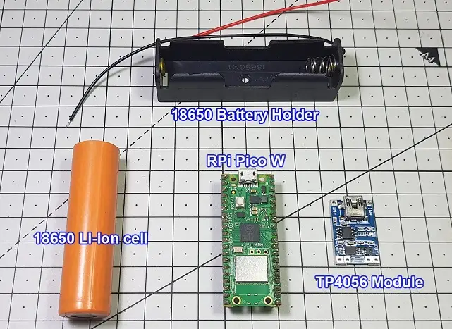
Components Required
- TP4056 Li-ion charge/discharge module.
- A 18650 Li-ion rechargeable battery.
- Single 18650 battery holder.
- A diode (Preferably Schottky diode).
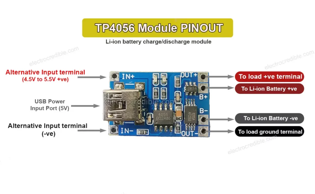
The TP4056 Module
The TP4056 is an IC used for safely charging a lithium-ion cell. The charge voltage is 4.2V and the charge current can be programmed with a single external resistor. The IC ensures that charging stops once a cell is fully charged. The maximum output current is 1A.
The TP4056 IC is commonly available in a breakout board module as shown in the image below.
Two kinds of TP4056 modules are available for purchase:
- One type only contains the TP4056 IC and some resistors, capacitors, and LEDs.
- The second type of TP4056 module also contains the DW01 and 8205 ICs along with other components.
For this project, ensure that the TP4056 module contains the DW01 and 8205 ICs onboard.
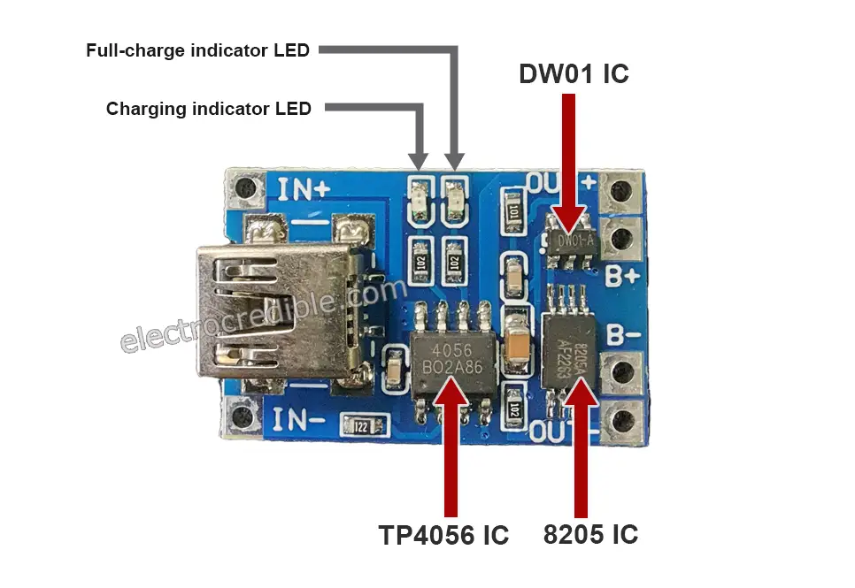
The DW01 IC is designed to protect a single lithium-ion/ lithium-polymer cell from overcharge, over-discharge, and/or overcurrent. The 8205A IC is a dual N-channel MOSFET IC that is suitable for battery protection circuits. The three ICs work together to safely charge/discharge a Li-ion battery.
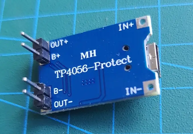
I soldered header pins to the TP54056 module for easy interfacing on a breadboard.
Schematic: Raspberry Pi Pico W with 18650 Battery & TP4056 Module
Connect the B+ and B- wires from the TP4056 board to the positive and negative ends of a Li-ion cell respectively. The OUT+ terminal goes to the VSYS pin of RPi Pico through a diode. The OUT- pin can be connected to any of the GND pins in Pico. The third pin from any corner of RPi Pico is a GND pin.
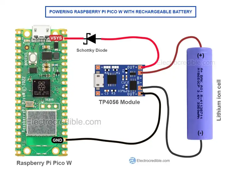
CAUTION: Maintain correct polarity while connecting the circuit components. Check the battery polarity with a multimeter/voltmeter before making any connections. Never short the wires connecting the battery.
Note that you may need to attach a USB cable to the TP4056 board for the initial power-up. When USB power is removed, the board will use the rechargeable battery to provide power output. You can also include a switch for convenience. Regarding usage while charging refer to this stackexchange link.
Running a Micropython Program On Battery
Your Raspberry Pi Pico needs to be preloaded with a MicroPython UF2 file to program it in MicroPython. You can read our getting started guide for Raspberry Pi Pico where we show all steps required to start programming RP2040 in MicroPython.
If you are using macOS, follow our guide to program Raspberry Pi Pico on macOS using Thonny IDE.
The following steps are explained using Thonny IDE, but you can choose any IDE you prefer.
Connect Pico to your computer using a USB cable. Open Thonny IDE, and paste the following code into a new project. The code will pulse the onboard LED in Raspberry Pi Pico W.
from machine import Pin
import time
led = Pin('LED', Pin.OUT)
while True:
    led.low()
    time.sleep_ms(500)
    led.high()
    time.sleep_ms(500)
Code language: JavaScript (javascript)- Go to File>Save as and select Raspberry Pi Pico as the save location.
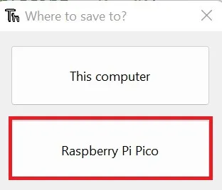
- Save the script as “main.py“.
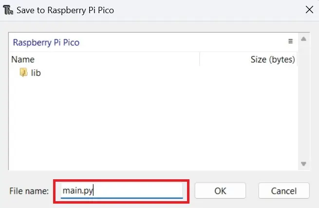
Note: To run a MicroPython script on Raspberry Pi Pico powered with batteries, it is necessary to save the script as main.py. If there is a boot.py file saved to Pico, then the boot.py script will run first followed by the main.py script.
After uploading the code, you can disconnect Pico from your computer and power it using batteries. When powered up, the onboard LED on Raspberry Pi Pico W should start blinking. In this way, you can save any code in the main.py file and the code will run as soon as Pi Pico boots.
Demonstration
The following image shows how I connected Pi Pico, a 18650 Li-ion battery, a TP4056 module, a diode, and an LCD on a breadboard.
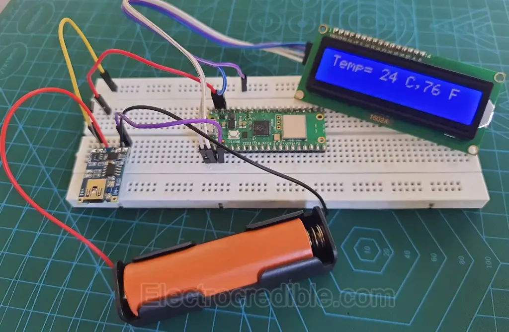
Most of the circuit is similar to the schematic discussed above. The LCD uses I2C to communicate with Raspberry Pi Pico W. The following code was saved as ‘main.py‘ to read the internal temperature sensor of Pico W and display it on the LCD. You can explore our articles on reading the internal temperature sensor in RPi Pico and interfacing an LCD to understand how the code works.
# Import necessary modules
import time
from machine import Pin, I2C, ADC
from lcd_api import LcdApi
from pico_i2c_lcd import I2cLcd

# Create an ADC (Analog-to-Digital Converter) object on pin 4
adc = machine.ADC(4)

# Define constants for the I2C LCD
I2C_ADDR     = 0x27
I2C_NUM_ROWS = 2
I2C_NUM_COLS = 16

# Create an I2C object and an I2C LCD object
i2c = I2C(0, sda=machine.Pin(0), scl=machine.Pin(1), freq=400000)
lcd = I2cLcd(i2c, I2C_ADDR, I2C_NUM_ROWS, I2C_NUM_COLS)

# Wait for the LCD to initialize
time.sleep(0.1)

# Infinite loop for continuous temperature monitoring and display
while True:
    # Read the ADC value and convert it to voltage
    ADC_voltage = adc.read_u16() * (3.3 / 65536)

    # Convert voltage to temperature in Celsius using a linear equation
    temp_celsius = 27 - (ADC_voltage - 0.706) / 0.001721

    # Convert Celsius temperature to Fahrenheit
    temp_fahrenheit = 32 + (1.8 * temp_celsius)

    # Clear the LCD display
    lcd.clear()

    # Display temperature in Celsius on the LCD
    lcd.move_to(0, 0)
    lcd.putstr("Temp=")
    lcd.move_to(6, 0)
    lcd.putstr(str(int(temp_celsius)))
    lcd.move_to(9, 0)
    lcd.putstr("C,")

    # Display temperature in Fahrenheit on the LCD
    lcd.move_to(11, 0)
    lcd.putstr(str(int(temp_fahrenheit)))
    lcd.move_to(14, 0)
    lcd.putstr("F")

    # Wait for 1 second before updating the display again
    time.sleep(1)
Code language: PHP (php)
Note that the LCD used in this demonstration should be powered with around 5V. Since the nominal voltage of a Li-ion battery is ~3.7V and the diode used will add a voltage drop, such lower voltage will create power issues with the LCD. So I powered the Pico VSYS pin through a diode but connected the LCD power pin directly to the output of the TP4056 module. This issue will not occur if we power Pico with a higher voltage supply as we shall see in the sections below.

Power Raspberry Pi Pico with 9V Battery
Powering Raspberry Pi Pico/Pico W with 9V batteries needs some additional circuits to step down the voltage. Since the VSYS pin needs a voltage in the range of 1.8V to 5.5V, we can step down the voltage from 9V battery to 3.3V or 5V in order to power Pico.
We shall see how we can convert the voltage from the 9V battery to 5V using a voltage regulator IC such as the LM7805. Powering Pico with 5V has some advantages such as:
- We can easily step the voltage down to 3.3V for use with 3.3V compatible sensors or devices.
- Interfacing 5V powered sensors/displays/devices becomes easier.
- The datasheet of Pico W also mentions that if we want to use Pico W in USB host mode, then we must power Pico W with 5V.
Components Required
- A 9V battery (non-rechargeable, commonly alkaline type).
- A 9V Battery clip connector.
- A 7805 linear voltage regulator IC.
- A Schottky diode.
- A Switch(Optional).
The LM7805 is a linear voltage regulator IC that provides a stable +5 Volt output from an unregulated input voltage of 7V to 35V. It comes with useful features such as current limiting and thermal shutdown.
Schematic: 9V Battery with RPi Pico W
The circuit diagram below shows a simple LM7805 used as a 9V to 5V converter. The voltage from the 9V battery is first converted into 5V by the LM7805 IC and this 5V is used to power Pi Pico through the VSYS pin. The diode can be of any type but Schottky diode is preferred due to its low voltage drop.
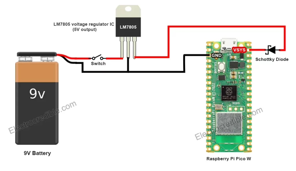
Generally, capacitors are recommended in both the input and output side of 7805 IC for stability. But this circuit will work fine without them as the 9V battery is a stable voltage source.
Demonstration
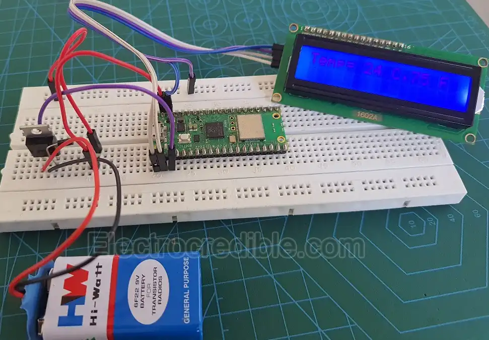
The image above shows how I connected Raspberry Pi Pico W with a 9V battery and a 7805 IC. Unfortunately, the image was captured when the LCD was refreshing. So the letters are not clearly visible. The code is the same as seen in the Li-ion example above.
Powering RPi Pico W with 6V, 12V, 24 V Batteries
For powering Pico with a 6V or a 12V lead acid battery, we can use the LM7805 IC as discussed in the section above. Another alternative is to use the LM317 linear regulator IC. The LM317 IC can be used with a wide range of batteries with a nominal voltage such as 6V, 9V, or 12V. Using just two external resistors, it is easier to set the output voltage of the IC.
Using LM317
The diagram below shows a simple voltage regulator circuit based on LM317.
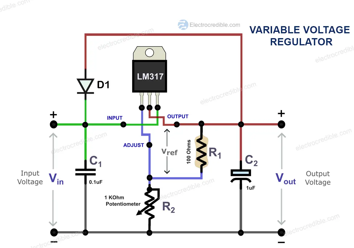
You can use a potentiometer (R2) to easily vary the output voltage or just use two resistors to get 5V or 3.3V for Pico. The output voltage of LM317 is given by the equation:
$V_{out}=1.25 \times (1+\frac{R_{2}}{R_{1}})$
For an output voltage of 5V, we use a 100 Ohm resistor as R1 and a 300 Ohm resistor as R2. The capacitors C1 and C2 can be omitted as well as the diode D1 (D1 is only needed when C2 is used. It provides a discharge path for C2).
A heat sink is recommended with the LM317 IC if it gets hot. However, you may choose to not use it as the power draw by the RPi Pico board will not be much. But use one if the LM317 IC becomes too hot to touch.
Using Buck Converter
An easy way to power Raspberry Pi Pico with different batteries is by using a buck converter. A buck converter is a switching regulator that can efficiently convert DC to DC. The LM2596 is one such popular buck converter that can convert input voltages up to 40 Volts to give an output voltage in the range of 1.2 V to 37 V.
The schematic below shows Raspberry Pi Pico powered using a 12V lead acid battery and an LM2596 Buck converter module.
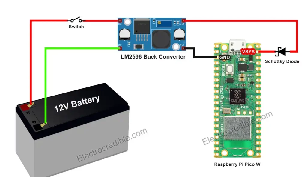
Before connecting Pi Pico to the buck converter module, first, adjust the output voltage of the buck converter. LM2596 module has a potentiometer onboard that can be adjusted to get variable voltage. Feed input voltage to the LM2596 module and adjust the potentiometer to get an output voltage in the range of 3.3 V to 5 V.
Power Raspberry Pi Pico With AA / AAA Battery Pack
Using AA/AAA batteries is the easiest and most cost-effective way to power a portable Raspberry Pi Pico project. AA and AAA cells have a nominal voltage of ~1.5V. Two or three such cells connected in series in a battery pack can power Raspberry Pi Pico. Here, we will connect three AA cells in series to get a voltage of ~4.5V (1.5×3).
The schematic below shows a 3-cell AA battery holder. The output wires from the battery holder are connected to the VSYS pin of Pico via a diode and a switch.
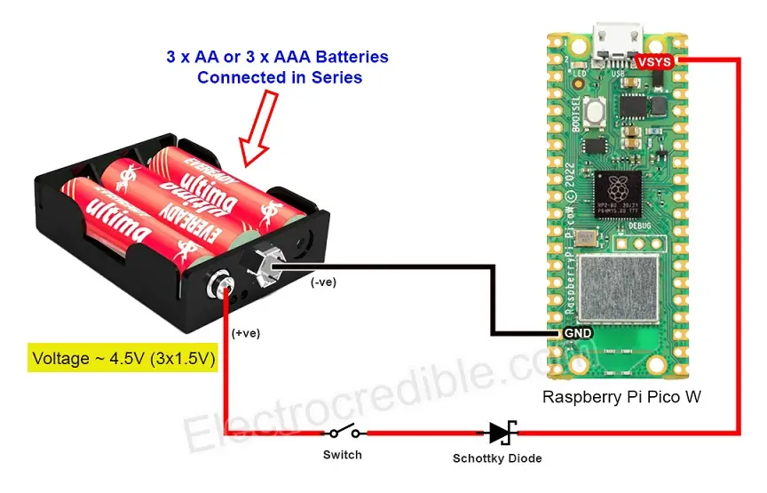
This is the simplest method to make your Raspberry Pi Pico projects portable and the component count is also low. Like the earlier examples, you can use a simple rectifier diode instead of a Schottky diode.
Demonstration
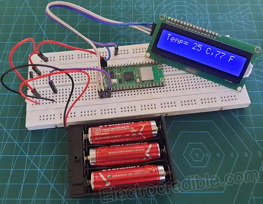
The following image demonstrates 3 AA batteries in series powering Raspberry Pi Pico. The same code is used as the examples discussed earlier to display temperature on an LCD.
Raspberry Pi Pico & Pico W Battery Life
The battery life of a Raspberry Pi Pico project will depend on how much current the Pico board and connected peripherals consume, and the capacity of the battery itself. Battery capacity is usually stated in milliampere-hour (mAH). A battery labeled “1000mAh” means the battery can theoretically provide a current of 1000 milliamperes (or 1 ampere) for one hour before its charge is depleted.
$Battery\:life (in\:hours)=\frac{Battery\:capacity (in\: mAh)}{Device\:current\:draw (in \:mA)}$
For example, if your Raspberry Pi Pico draws a constant current of 100mA, a 1000mAh battery should last approximately 10 hours before needing to be recharged.
$Battery\:life=\normalsize \frac{1000\:mAH}{100\:mA}= 20\: hours$
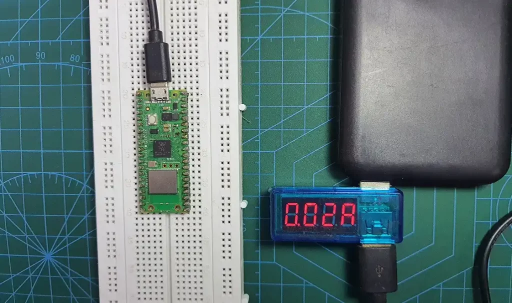
I loaded a simple web server script on Pico W and measured its current draw using a ‘USB doctor’ device. The ammeter in the device showed a current consumption of 0.02 Amps or 20mA. So if we use a battery of capacity 1000 mAH, the battery should theoretically power Pico W for around 50 hours.
Conclusion
Except for the TP4056 circuit, the other circuits discussed in this article do not take care of battery discharge monitoring. While powering from a 9V battery or AA battery, your Pico will shut down when the battery discharges beyond a certain voltage. You can implement battery voltage monitoring using the ADC in Raspberry Pi Pico to prevent Pico from shutting down abruptly.
In this guide, we discussed various ways to power Raspberry Pi Pico using batteries. Example circuits were shown for Li-ion, 9V alkaline, AA, AAA, and lead acid batteries. Hope you found the article to be helpful. You can follow our guide to make a simple weather station using BME280 and make an awesome portable Raspberry Pi Pico project.
Leave a Reply