In this article, we will learn how an adjustable/variable voltage regulator works, and how we can make various kinds of variable voltage regulator circuits.
A voltage regulator is a circuit that provides a consistent output voltage regardless of changes in input voltage or load. It is an essential building block used to supply power to electronic devices. A variable voltage regulator makes it possible to adjust the output voltage within a certain range. This makes it ideal for applications such as a variable bench power supply.
Although a voltage regulator can be made using discrete electronic elements such as operational amplifiers and transistors, we will see how we can use readily available ICs, such as the LM317 or the LM337, to make adjustable regulators easily. Both positive and negative variable voltage regulators will be discussed along with their circuit and an explanation of how they work.
Working of a Variable Voltage Regulator
A linear variable voltage regulator can be constructed with the following components:
- A Reference Voltage: An internal stable voltage reference (example: Zener diode) is used as a reference for an error amplifier.
- Sampling Circuit: Gives a feedback voltage to an error amplifier.
- Error Amplifier: It compares the feedback voltage with the reference voltage and controls a pass element to get to a fixed output voltage.
- Pass Element: The pass element (e.g. a transistor) acts as a variable resistance and drops the excess voltage across it. The output voltage is obtained at one terminal of the pass element.
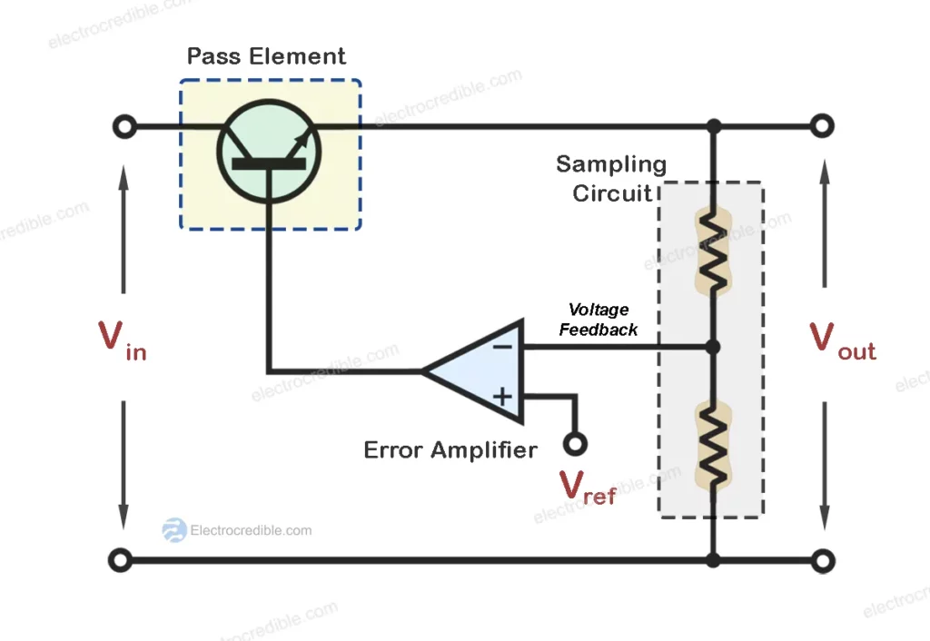
Figure 1 shows the block diagram of a simple variable voltage regulator. A voltage divider feeds the output voltage to an error amplifier. The error amplifier compares this voltage with a reference voltage Vref. The error amplifier then controls the pass element Q1 to get the regulated output voltage.
This working principle is used in many linear integrated circuits which gives a voltage regulator in a small form factor.
Using LM317 For Variable Voltage Regulator
LM317 linear voltage regulator is a commonly used IC that regulates voltage by dissipating excess power as heat. LM317 can output regulated voltage from 1.25 V to 37 V. The maximum output current of the IC is 1.5 A.
The voltage regulator IC also features current limiting, thermal overload protection, and safe operating area (SOA) protection. This feature helps in minimizing external components required for a DIY voltage regulator to function.
Given below in Figure 2 is the pinout of LM317:

Variable Voltage Regulator Circuit Diagram
The circuit diagram in Figure 3 shows a DIY variable voltage regulator circuit that can be constructed using the LM317 IC. It is a DC-to-DC voltage converter that can convert a DC voltage at the input to a lower DC voltage at the output.

Although two external resistors along with the LM317 IC will be enough to get a regulated output voltage, some additional components are also required for the stable and safe operation of the regulator as explained below:
- A 100 Ohm Resistor and a 1-KOhm potentiometer. These are used to set the output voltage.
- Cin is a 0.1 uF capacitor bypass capacitor.
- Cout is a 1 uF capacitor. It improves the transient response of the regulator.
- Diode D1 is required to provide a discharge path for the Cout capacitor. Without it, the capacitor may discharge into the output of LM317 in the absence of a load.
The voltage at the output is given by the formula:
$V_{out}=1.25 \times (1+\frac{R_{2}}{R_{1}})$
The table shows how we can get some standard voltages by using different values for R2 and by choosing R1 as 100 Ohms.
| R1 (Ohms) | R2 (Ohms) | Output Voltage (Volts) |
| 100 | 164 | 3.3 |
| 100 | 300 | 5 |
| 100 | 620 | 9 |
| 100 | 860 | 12 |
| 100 | 1820 | 24 |

Design Considerations for LM317 Variable Voltage Regulator
The input voltage to the LM317 voltage regulator should be at least 3 Volts more than the output voltage. For example, if we require 12 Volts at the output, the input voltage must be higher than 15 Volts. Also, the difference between the input voltage and output voltage should not be more than 40 V.
The voltage rating of the capacitor Cin should be higher than the input voltage and the voltage rating of Cout needs to be higher than the output voltage.
The diode D1 can be any of the commonly used rectifier diodes such as the IN4002 or the IN4007.
As the LM317 IC wastes the excess power as heat, it is advised to use an appropriate heat sink with the IC. Without a proper heatsink, the IC may be affected by thermal shutdown.
How to Select the Resistors for LM317 Voltage Regulator?
The datasheet of LM317 mentions 10 mA as the minimum load current to maintain regulation. In case the load current falls below 10 mA, the current through R1 can help to pass the required minimum current for load regulation.
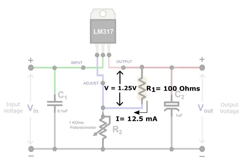
The voltage across the R1 resistor is always 1.25 V due to an internal voltage reference in the IC. For 10 mA current to flow through R1, we can apply Ohm’s law to find the value of R1 as:
$R_{1}=\frac{1.25\; V}{10\; mA}$
$R_{1}= 125\; Ohms$
Hence for effective regulation, you choose the value of R1 to be 100 Ohms. In this case, the current through R1 will be around 12.5 mA, which meets the minimum current criteria of 10 mA.
High Current Variable Voltage Regulator Using LM317
The variable voltage regulator circuit that we discussed in Figure 3 can only output a maximum current of around 1.5 A. To get a higher current using LM317 IC, we need to add an external pass element such as a high current-rated transistor. Take a look at the high current variable voltage regulator shown below in Figure 4.

Q1 is a PNP transistor and Q2 is an NPN transistor. R5 is used to limit the base current to Q1. When current passes through the resistor R4, a voltage drop occurs across it. The voltage across R4 turns on the Q1 transistor. As a result, current starts flowing through the resistor R6. The voltage developed across R6 now turns on transistor Q2. Hence, current flows from the collector to the emitter of Q2 and reaches the output.
Q2 needs to be rated for high collector current. A bipolar power transistor such as the TIP41 can be used as Q2.
BC557 PNP transistor can be used as Q1. It has a base-emitter ON voltage of around 700 mV. So to turn on Q1 the voltage across R4 needs to be at least 700 mV. By Ohm’s law, we can find the current through R4 as 700 mV / 22 Ω = 31.81 mA. So, the load must draw at least 32 mA for this high current variable voltage regulator to function properly.
Variable Linear Power Supply Circuit
A simple AC to DC variable linear power supply circuit can be made using a step-down transformer and full wave rectifier along with the LM317 variable voltage regulator circuit.

In the circuit diagram above, 220 V AC is fed to the primary of the transformer. The transformer steps down the voltage from 220 V AC to 12 V AC. This 12 V AC is fed into the full-wave rectifier, which converts the AC to DC. The output voltage will be less than 12 V in this case and will depend on the value of resistances R1 and R2.
The rectified voltage is then connected to the input terminals of the LM317 to give a variable DC voltage at the output.
Variable Negative Voltage Regulator
To make an adjustable negative voltage regulator, we can use the LM337 IC or the LM137 IC. These are linear voltage regulator ICs that can output regulated voltage in the range of -1.25 Volts to -37 Volts. Just like the LM317, they feature internal current limiting and thermal shutdown.
LM137/LM337 IC only requires an external resistor and a potentiometer to give regulated negative voltage. Adding capacitors at the input and output will also improve stability and transient response.
The circuit diagram of an adjustable negative voltage regulator is shown below:
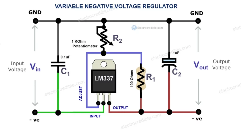
The voltage at the output can be approximated by the formula:
$V_{out}=-1.25 \times (1+\frac{R_{2}}{R_{1}})$
A Dual Variable Voltage Supply
With the information we learned so far in this article, we can now easily construct a dual variable power supply. The positive voltage can be regulated and varied using the LM317 IC and the negative voltage can be regulated using LM337 or the LM137 IC.
We will also need a center-tapped transformer to get both positive and negative voltages.
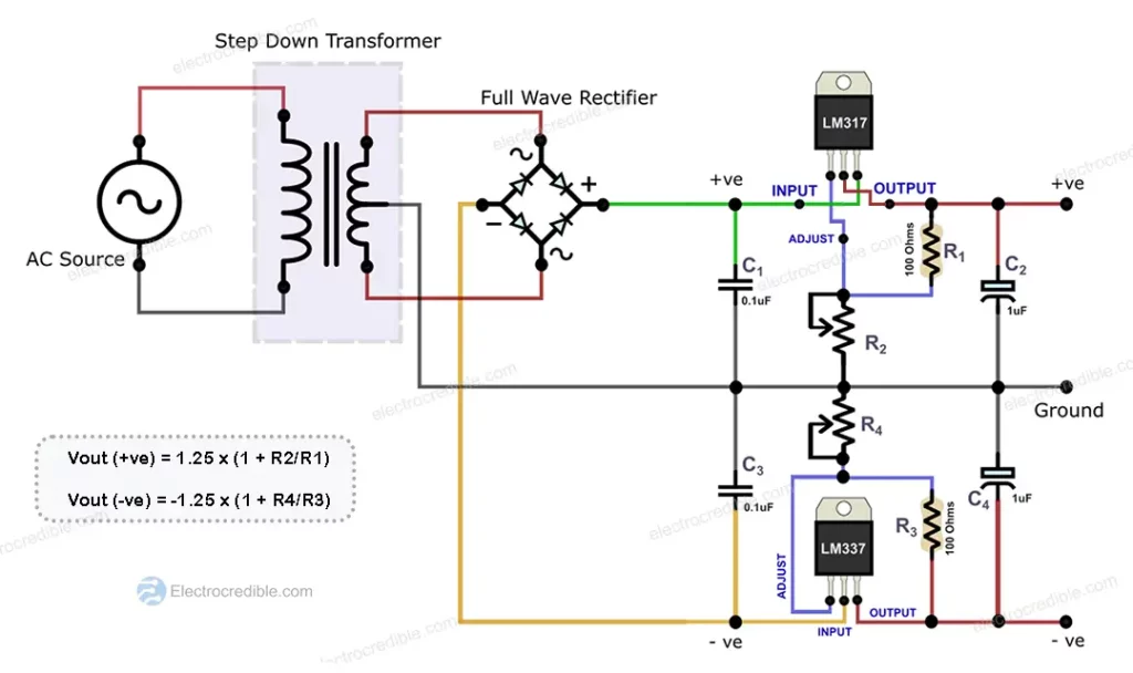
This circuit can be used to construct a variable lab voltage regulator. It can be used to power operational amplifiers that require dual rail supply and audio amplifiers such as class AB amps that require both positive and negative rails.
Variable Voltage Regulator IC List
Apart from the LM317 we discussed in this article, here is a list of some commonly used voltage regulator ICs that can be used depending on your application:
- LM117: LM117 is a low dropout (LDO) variable voltage regulator with variable output voltage in the range of 1.25 V to 13.8 V. Only two external resistors are required for setting the output voltage. It has a maximum dropout voltage of 1.3 V at 800 mA.
- LM338: This positive voltage regulator IC can output in excess of 5 A over the 1.2 V to 32 V output range.
- LM350: LM350 is an adjustable high current variable voltage regulator IC. It can output 3 A over an output voltage range of 1.2 V to 33 V.
- LM1085: It is an adjustable LDO regulator that can source up to 3 A of current and requires only two external resistors.
Leave a Reply