A voltage divider or potential divider is an important building block in electronic circuits. This simple circuit can take an input voltage and convert it into an output voltage which is a fraction of the input voltage. The value of the output voltage is determined by the circuit elements such as resistors, capacitors, or inductors.
The circuit below shows three kinds of voltage dividers that we can construct using passive electronic components. Each of these circuits will be discussed in detail in this article.
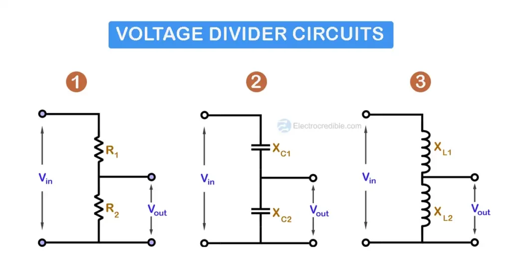
The resistive voltage divider is the most widely used voltage divider circuit.
Resistive Voltage Divider Circuit
A resistive voltage divider is made by connecting two or more resistors in series across a voltage source. Let us look at a simple voltage divider constructed using two resistors in series.
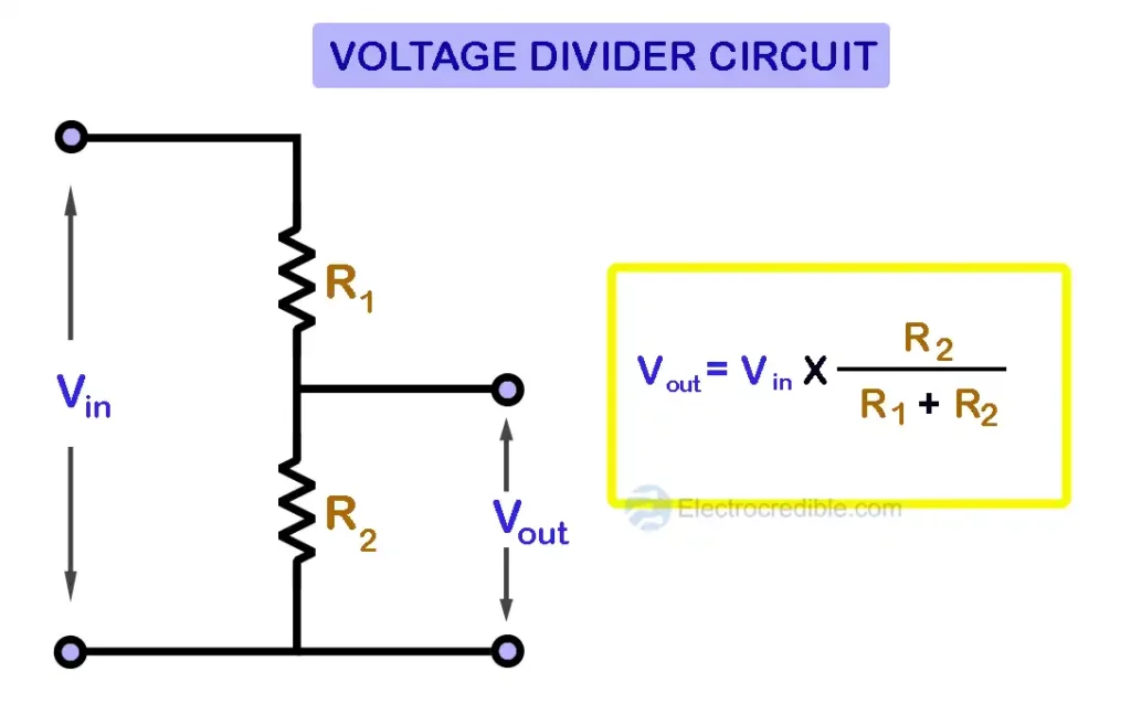
The input voltage Vin is applied across the two resistors R1 & R2 which are connected in series. The output voltage Vout is obtained between the two terminals of the resistor R2. The voltage across this resistor will be a fraction of the input voltage Vin.
The formula to calculate the output of a voltage divider with two series resistors is:
$V_{out}= Vin\;\times\;\left( \frac{R_{2}}{R_{1}+ R_{2}} \right)$
The general formula for a resistive voltage divider is:
$V_{out}= Vin\;\times\;\frac{R_{x}}{R_{t}}$
Where Rx is the resistor across which the Vout is obtained, and Rt is the total resistance of all the resistors connected across the supplied voltage Vin.
Voltage Divider Example – Multiple Resistors in Series
When multiple resistors are in series, the voltage across each resistor is proportional to its resistance. Consider the example shown in Figure 3 with three resistors 6 kiloohms, 4 kiloohms, and 10 kiloohms connected in series across a battery with a voltage of 12V.

We can apply the formula of voltage division to find the voltage across each resistor. For the given voltage divider circuit, the output (Vout) is desired across the 10-kiloohm resistor.
$ V_{out}= 12\;\times\;\left(\frac{10_{K\Omega}}{4_{K\Omega}+6_{K\Omega}+10_{K\Omega}} \right)$
$\Rightarrow V_{out}= 6\;V$
Similarly, we can find that the voltages across the 6-kiloohms and the 4-kiloohms are 3.6 V and 2.4 V respectively. This is also in accordance with Kirchhoff’s Voltage Law, which states that the algebraic sum of all voltages around any closed loop must be equal to zero, or Σ V = 0. In our example, we can apply KVL with sign convention and find that Σ V = 12V- 3.6V-2.4V-6V = 0.
Applications of Resistive Voltage Divider
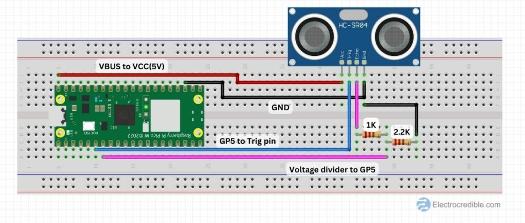
- Voltage dividers can be used to interface microcontrollers and sensors that require different supply voltages. For example, in a project where we interfaced a distance sensor with Raspberry Pi Pico, a voltage divider was used to step down the voltage output of the HC-SR04 sensor to around 3.3V required by Raspberry Pi Pico W.
- We can use voltage dividers in place of logic level converters for interfacing devices that operate at different logic levels.
- Potentiometers operate on the principle of voltage division. It is a variable voltage divider.
- Biasing of transistors is often done with voltage dividers.
- Monitoring of battery voltage can be done using a voltage divider circuit. For example, if we wish to measure the voltage of a 12V lead acid battery using an Arduino UNO board, we need to step this voltage down to the range of 0 to 5V DC. We can do so by selecting two appropriate resistors so that an input voltage of 12V to the voltage divider will give us an output of 5V.
Capacitive Voltage Divider Circuit
Just as resistance is a property of resistors to measure how much a resistor opposes the current through it, capacitive reactance (X) is a property of a capacitor to measure its opposition to alternating current. Due to its reactance, the capacitor behaves as a low resistance path for AC current but blocks DC current.
The capacitive reactance of a capacitor is given by the formula:
$X_{C}=\frac{1}{2\;\Pi\;f\;C}$, where Xc is the capacitive reactance in Ohms, π is the mathematical constant(3.1415..), f is the frequency in Hertz and C is the capacitance in Farads.
Consider two capacitors that have capacitance C1 and C2 and reactance XC1 and XC2 respectively. The voltage divider circuit of the two capacitors in series is shown in Figure 5 below.

In the diagram, Vout is the output voltage of the voltage divider which is the same as the voltage across VC2. The capacitive voltage divider formula is:
$V_{out}= Vin\;\times\;\left( \frac{X_{C2}}{X_{C1}+ X_{C2}} \right)$

Inductive Voltage Divider Circuit
Inductive reactance is a measure of the opposition of an inductor to the flow of AC current to it. The inductor behaves like a short circuit for DC currents but opposes alternating current through it.
The inductive reactance of an inductor is given by the formula:
$X_{L}=2\Pi fL$ , where XL is the inductive reactance in Ohms, π is the mathematical constant(3.1415..), f is the frequency in Hertz and L is the inductance in Henry.
Consider two inductors that have inductances L1 and L2 with reactance XL1 and XL2 respectively. The voltage divider circuit of the two inductors in series is shown below in Figure 6.

The formula of an inductive voltage divider is:
$V_{out}= Vin\;\times\;\left( \frac{X_{L2}}{X_{L1}+ X_{L2}} \right)$
Wrapping Up
In this article, we discussed different kinds of voltage divider circuits. The resistive divider has some drawbacks. Most importantly, it will not be able to provide a steady voltage if the load has a low input impedance. So voltage dividers should not be used as power supply.
The stability of a voltage divider can be improved using a voltage buffer circuit that can be made using a transistor or an operational amplifier. The buffer circuit or a voltage follower will be able to source significantly more current than the simple resistive voltage divider.
Also Read: Kirchhoff’s Current Law (KCL) Explained
Leave a Reply