Kirchhoff’s Voltage Law (KVL) is a fundamental principle in electrical circuit analysis, named after the German physicist Gustav Kirchhoff. KVL states that the total voltage around any closed loop in an electrical circuit is equal to zero at any instant in time. In an electric circuit, a ‘loop’ is a closed path formed by one or more electrical components or wires. Kirchhoff’s Current Law(KCL) and KVL are two of the most important laws used in electrical network analysis.
KVL is based on the principle of conservation of energy, which dictates that energy cannot be created or destroyed, only converted from one form to another. KVL is applicable to both AC and DC circuits.
Mathematical Expression Of KVL
According to Kirchhoff’s voltage law, “In a lumped electric circuit, the algebraic sum of all voltages around any closed loop must be equal to zero at any point of time”. Note the significance of the term “algebraic sum” which denotes that we add the voltages while taking account of their signs. In a lumped circuit, the electrical components are assumed to be ideal and the connecting wires are assumed to be of zero resistance.
Mathematically, KVL can be expressed as:
Σ V = 0, where ‘Σ V’ denotes the summation of voltages around a closed loop in an electrical circuit.
Sign Convention in KVL
The voltage across each element in a loop must be given a positive or negative sign in order to apply KVL. Sign convention determines the polarity of the element’s voltages while writing the KVL equation. By following this convention, we ensure that the algebraic sum of all voltages around any closed loop in the circuit is equal to zero.
Let us consider a simple circuit with a voltage source Vs, two resistors R1 and R2, and an inductor L. The following procedure can be used to assign the sign for voltages across each element:
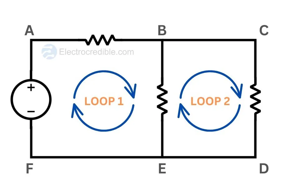
- Assign a direction of current in the loop, either clockwise or anti-clockwise. For example, we assign a clockwise direction to the current in the figure below.

- Assign a +ve sign to the terminal of an element where the current enters and a -ve sign to the terminal where the current leaves. If there is a voltage source in the loop, its sign is the same as its polarity.

ⓘ To make it easier to remember, think that we assign +ve sign to the terminal which is at a higher potential and vice versa.
KVL Equation By Following Sign Convention
Let us now see the steps to form an equation of voltages using KVL.
- Pick a starting node and travel along a loop in the direction you chose earlier. Let’s select the positive terminal of the battery as the starting node in the circuit below and travel in the clockwise direction. Also choose appropriate labels for voltages across components, such as VR1 for the voltage across resistor R1.

- If we encounter an element with a +ve sign first, subtract its voltage in the KVL equation(i.e. potential drop occurs across the element). Likewise, if the first sign we encounter is -ve while we arrive at an element, we add its voltage.
The KVL equation for Figure-3 can be thus written as:
-VR1-VL-VR2+VS=0
The first element is the resistor R1 and we consider its voltage as ‘-VR1‘ as we encounter the +ve sign of this element when moving in our selected direction. Similar logic is followed for the inductor L and resistor R2.
For the voltage source, we consider its voltage as ‘+VS‘ because we enter the element through the -ve terminal when traveling along the loop.
Alternative sign conventions can also be used in KVL. For example, when a +ve sign is encountered, we can add the element voltage while writing the KVL equation and vice-versa.
Leave a Reply