This tutorial will guide you to interface an LDR/photoresistor with Raspberry Pi Pico W. LDR (Light Dependent Resistor) is an electronic sensor commonly used in electronic circuits for applications such as light-sensitive switches.
MicroPython code is used here to read analog values from an LDR. Detailed steps are shown to control AC appliances based on light sensed by LDR.
Components Required
- Raspberry Pi Pico or Pico W.
- An LDR.
- A 10kΩ resistor.
- Breadboard and connecting wires.
- 5V Relay module (optional).
Brief Overview- LDR or Photoresistor
A Light Dependent Resistor (LDR) is a photoconductive device whose electrical resistance varies with light intensity. LDRs are commonly used in devices like automatic streetlights that get triggered on/off based on sunlight.
When there’s a lot of light, the LDR’s resistance decreases. In other words, it allows more electric current to flow through it. In low light or darkness, the LDR’s resistance increases, restricting the flow of electric current.
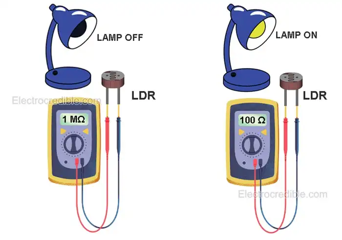
You can test a photoresistor by setting your multimeter to the resistance sensing position and connecting the multimeter leads to the legs of the LDR. See how the resistance changes when you cover the sensor with your hand. When I tested in total darkness, the resistance was more than 1 megaOhm. When the LDR was moved close to a light bulb, its resistance dropped to around 100 Ohms.
Photoresistors are also available as modules as shown below. These modules come with an onboard potentiometer, comparator, and other passive components so it becomes easy to interface.
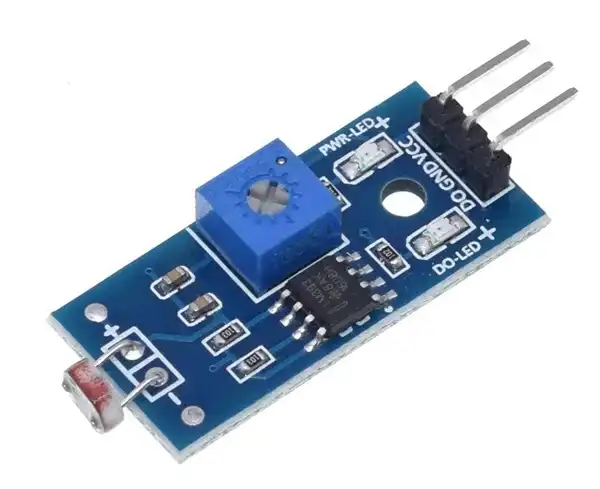
Such LDR modules can control relays without the need for a microcontroller. However, setting the threshold can be tricky through trial and error.
How to Read LDR Using Raspberry Pi Pico
Due to the resistive nature of a photoresistor, we can use it in series with another resistor to form a voltage divider.
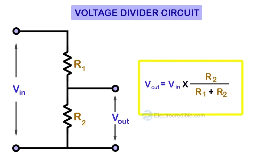
Instead of R1, we will connect the LDR. A 10kΩ resistor will replace R2.
The output of a voltage divider depends on the total voltage supplied across the resistors and the value of the resistors. As the resistance of an LDR changes with the intensity of light falling on it, we will get a variable output voltage depending on light intensity. This voltage can be measured by Raspberry Pi Pico with the help of an ADC.
ADC( Analog-to-digital converter) are circuits that help to read real-world analog voltages by converting them to digital data. Raspberry Pi Pico/Pico W has three pins for ADC that give access to three inbuilt ADCs.
| ADC Channel | GPIO Pin |
| ADC0 | GPIO 26 |
| ADC1 | GPIO 27 |
| ADC2 | GPIO 28 |
To learn more about ADC, read how to use the ADC in Raspberry Pi Pico.

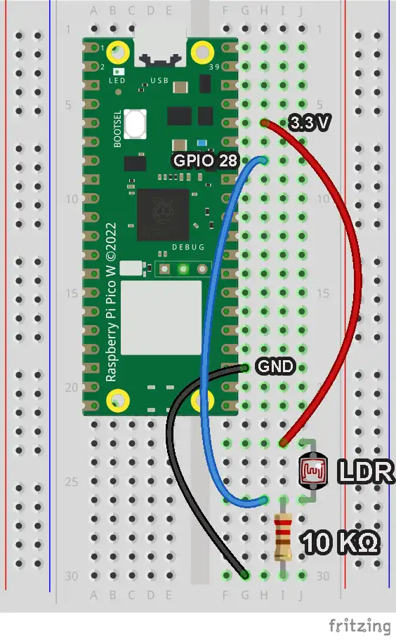
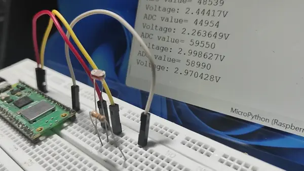
Wiring LDR with Raspberry Pi Pico
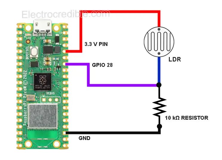
Connect one terminal of the LDR to the 3.3 volts output pin onboard Raspberry Pi Pico. Connect the other terminal of the LDR to one terminal of a 10kΩ resistor. The remaining terminal of the 10kΩ resistor connects to the Ground. (Tip: The third pin from any corner of Raspberry Pi Pico is a GND pin).
We have used GPIO 28 to read the output of the voltage divider, but you can also use GPIO 26 or GPIO 27. GPIO 28 is the 7th pin from the top right corner of Pico.
LDR MicroPython Code
Raspberry Pi Pico needs to be flashed with a MicroPython UF2 file to program it in MicroPython. You can read our getting started guide for Raspberry Pi Pico where we show all the steps required to start programming Raspberry Pi Pico & Pico W.
The steps to upload MicroPython code are explained using Thonny IDE.
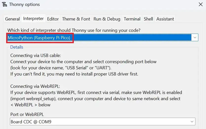
1. With all connections done according to the above schematic, connect the Pico to your computer using a USB cable. Open Thonny IDE and set the interpreter to use MicroPython on Raspberry Pi Pico.
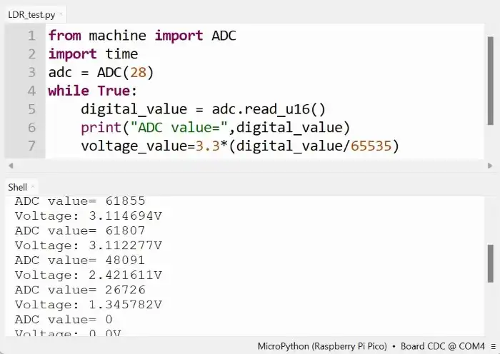
2. Paste the following code into a new project.(File>New in Thonny IDE)
from machine import ADC
import time
adc = ADC(28)
while True:
digital_value = adc.read_u16()
print("ADC value=",digital_value)
volt=3.3*(digital_value/65535)
print("Voltage: {}V ".format(volt))
time.sleep(1)
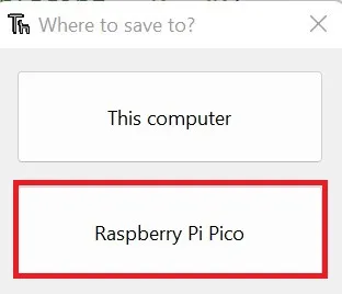
Code language: Python (python)3. Click on File>Save as and select the save location as Raspberry Pi Pico.
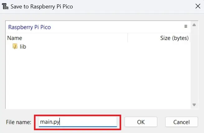
4. Name the code file as main.py.
5. Run the code by clicking the Run icon or by pressing the F5 key.

Now, in the shell of Thonny IDE, you can view the output voltage from the voltage divider connected to the LDR.
You can also view the plot of ADC value in the inbuilt plotter of Thonny IDE. Click on View>Plotter to view the plotter. Here is a screenshot of the plotter showing ADC data when I covered the light sensor with my hand and then removed the hand after a few seconds:
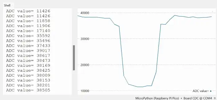
Note: Only print one value for plotting. Comment out other print statements from your code.
Understanding Data from the Photoresistor
If you move the photoresistor from light to darkness, the output voltage printed in the shell of your IDE will change from a higher value to a lower value.
The formula for the output voltage of the voltage divider formed by series resistors R1 & R2 is:
$V_{out}= Vin\;\times\;\left( \frac{R_{2}}{R_{1}+ R_{2}} \right)$
Here, the photoresistor replaces R1. The 10kΩ resistor replaces R2. The resistance of the LDR (R1) increases when moving from a well-lit area to a dark one. So, the output voltage of the voltage divider will decrease. This is evident in the output printed in the shell of the IDE.
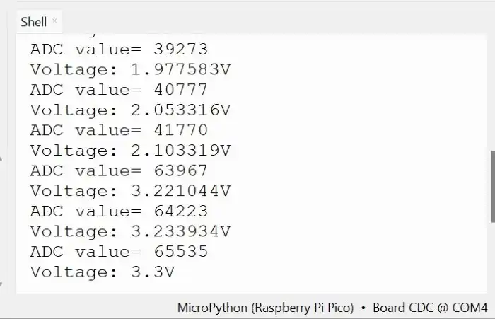
The image below shows the output when LDR is moved from a dark area to a bright area – the voltage read by ADC increases.
Demonstration
The animation below demonstrates how the output in the shell of Thonny IDE varies as I change the amount of light falling on the photoresistor.
Sense Light/ Darkness using LDR & Raspberry Pi Pico W
We can apply the methods described so far to build projects such as automatic lights. Such lights can switch on/off automatically according to ambient light.
Here are two examples of how we can control AC appliances that can turn off when the LDR detects light or darkness.
Dark/Light Detector Circuit- Control AC Appliances
To control AC appliances, we need to interface with a relay module. Relays are electromechanical switches that help to interface low-voltage devices such as microcontrollers to high-voltage devices such as AC bulbs or fans.
Take a look at our guide on interfacing relays with Raspberry Pi Pico where we thoroughly explain how to control relays.
We shall use a commonly available relay module as shown below. A single-channel relay module will work, but here we have explained using a 2-channel relay.
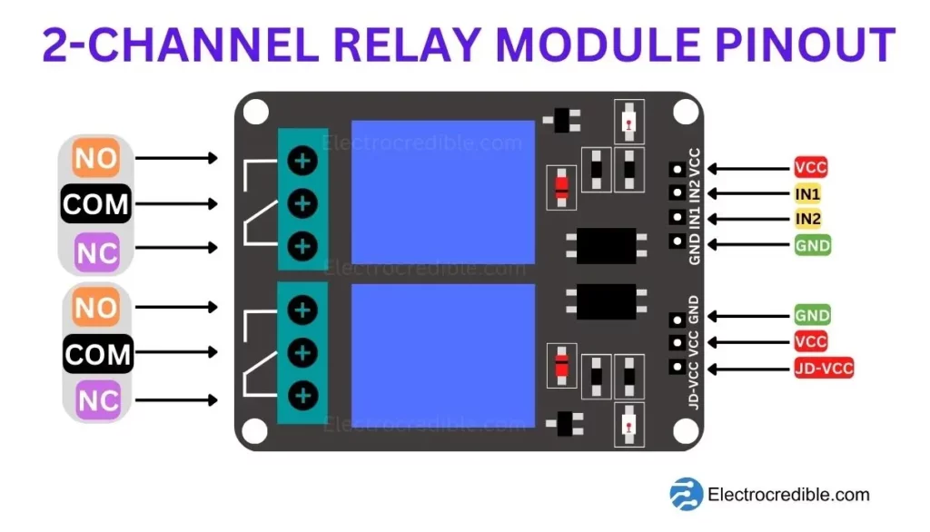
Each channel of a relay module lets us control an appliance independently. The common pin (COM) either makes contact with the NO or NC terminal, depending on the state of the relay. When the relay is not powered, the Normally Open (NO) terminal stays open and the Normally Connected (NC) terminal is shorted to COM. The reverse condition occurs when the relay is powered.
The two input pins IN1 and IN2 control the two relays. Connecting these pins to the ground(or VCC in some modules) will switch on the respective relays.
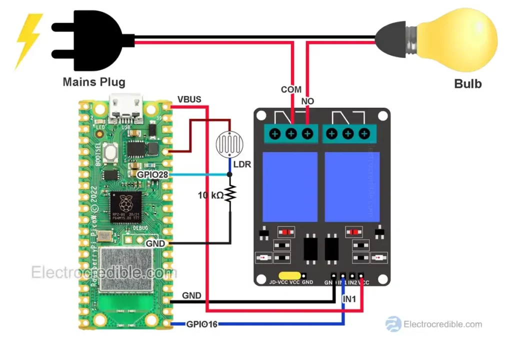
Schematic: Photoresistor-controlled AC Bulb
The relay module is powered from 5V via the VBUS pin of Pico W. GPIO 16 sends the control signal to the relay. One relay out of the two is left unused.
Dark Sensor MicroPython Code
from machine import ADC, Pin
import time
adc = ADC(28) #pin to read LDR
relay_pin=Pin(16, Pin.OUT) #pin connected to relay module
while True:
    digital_value = adc.read_u16()
    volt=3.3*(digital_value/65535)
    if volt<1:
        relay_pin.value(0) #turns on the relay
    if volt>1.2:
        relay_pin.value(1) #turns off the relay
    time.sleep(1)Code language: Python (python)
This MicroPython code will switch on the AC bulb when the light falling on the LDR goes below a certain threshold. If the light intensity crosses another threshold, the bulb will switch off.
The reason for including two threshold values in the code is to add hysteresis. Otherwise, the bulb may oscillate between on and off states when the value is close to the threshold.
Note that the code relay_pin.value(1) turns off the relay. Usually, a relay module turns off when we send +5V to the input pin. But you may also find some modules that turn off by the code relay_pin.value(1).
Light Sensor MicroPython Code
The same code as above may be slightly modified if we want to turn off an appliance when light falls on the photoresistor.
from machine import ADC, Pin
import time
adc = ADC(28) #pin to read LDR
relay_pin=Pin('LED', Pin.OUT) #pin connected to relay module
while True:
    digital_value = adc.read_u16()
    volt=3.3*(digital_value/65535)
    if volt<1:
        relay_pin.value(1) #turns off the relay
    if volt>1.2:
        relay_pin.value(0) #turns on the relay
    time.sleep(1)Code language: Python (python)
Conclusion
In this guide, we discussed how we can interface an LDR with Raspberry Pi Pico W. We also explained a basic application circuit that can detect light/darkness and control AC appliances such as home lighting.
You may use this information to build more projects such as solar panel sun trackers, automatic curtains, automatic night lamps, etc.
Leave a Reply