In this guide, we will learn how to use the ADC in Raspberry Pi Pico W and read voltages using the onboard GPIO. ADC stands for Analog To Digital Converter. ADC is a circuit that can convert analog data(such as voltages) to digital data(i.e. 1’s and 0’s).
Sensors are used to sense real-world signals like sound, temperature, pressure, etc. , and output the sensed readings as a varying analog voltage. This voltage is converted by an ADC for further processing in digital systems such as microcontrollers. Here, we will use MicroPython to demonstrate how we can use the ADC in Raspberry Pi Pico W to read the voltage in a potentiometer.
Raspberry Pi Pico ADC Pinout
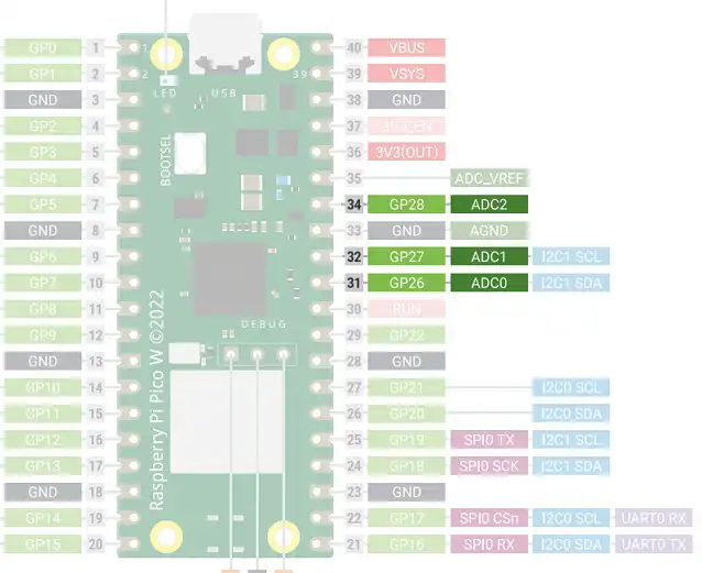
A total of 5 ADC (Analog-to-Digital Converter) channels are available on the RP2040 microcontroller. Through GP26, GP27, GP28, and GP29, respectively, you may access ADC0, ADC1, ADC2, and ADC3. However, GP29 is a special function pin that is not accessible via the Pi Pico board pinout pads.
These four ADCs use a 12-bit SAR type of ADC. An internal temperature sensor is coupled to the fifth ADC channel. These ADCs detect analog voltages between 0 and 3.3 volts.
The following table shows the GPIOs and the corresponding ADC channels that we can access through the pinout.
| ADC Channel | GPIO Pin |
| ADC0 | GPIO 26 |
| ADC1 | GPIO 27 |
| ADC2 | GPIO 28 |
Take a look at the pinout of Raspberry Pi Pico W below to locate the ADC pins.
Specifications of the ADC in Raspberry Pi Pico & Pico W
Here are the specifications of Raspberry Pi Pico W ADC:
- ADC Resolution: 12-bit.
- Sampling frequency: 48Mhz.
- ADC max voltage: 3.3V
The RP2040 ADCs employ an independent 48Mhz clock and sample at a rate of 500kS/s. It takes 96 clock cycles for each sample. So, (96/48Mhz)= 2μS is the sampling time required for each sample. The datasheet also mentions that the ADC inputs in Pi Pico are capacitive. When voltages are sampled, the ADC places about 1pF capacitance across the input.
ADC Resolution
The resolution of an ADC is the smallest change in analog voltage for which there occurs a change in the digital reading. from the 12-bit ADC registers in Pi Pico, we will receive a number ranging from 0 to 4095 (2^12-1). However, certain MicroPython routines can scale the ADC values so that they fall within a 16-bit range. As a result, we obtain ADC values in the 0 to 65535 (2^16-1) range, as we will see in an example below.
ⓘ Please ensure that the voltage at the ADC input pins stays within 0 V to 3.3V. If required, use a voltage divider to bring down higher voltages within the range of 0-3.3V.
Raspberry Pi Pico ADC Example- Read Potentiometer
Components required for this example:
- A Raspberry Pi Pico running MicroPython.
- One 10 kiloohm potentiometer. You can also try other potentiometers in the kiloohm range.
- Breadboard & connecting wires.
If you have not preloaded the MicroPython UF2 file on your Pico, you can refer to our guide- Getting Started With Raspberry Pi Pico & Raspberry Pi Pico W Using MicroPython.
Connect your Pi Pico to a potentiometer as shown in the diagram below.
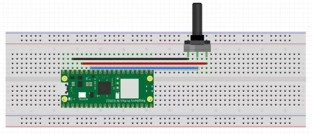
We are using GP28 i.e. the ADC2 channel of Pi Pico for this example. The outer pins of the potentiometer are connected to 3.3V and GND, and the middle pin is connected to GP28 of Raspberry Pi Pico.
MicroPython Code to Read Potentiometer Using ADC in Raspberry Pi Pico W
- Open a new project in Thonny IDE and paste the following code in the editor space.
from machine import ADC
import time
adc = ADC(28)
while True:
    digital_value = adc.read_u16()
    print("ADC value=",digital_value)
    voltage_value=3.3*(digital_value/65535)
    print("Voltage: {}V ".format(voltage_value))
time.sleep_ms(500)Code language: Python (python)- Run your code by pressing F5 or the green Run icon.

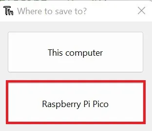
- Save the script to your Raspberry Pi Pico
- Name the file adc_example.py or any other name with a ‘.py’ filename extension.
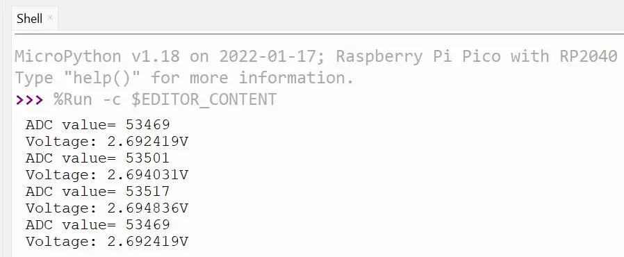
When you run your code, the Shell window in Thonny will display the ADC values as shown in the image below.
ADC Code Explained
At first, we import the ADC class from the machine module. The ADC class contains predefined functions to sample analog voltage and convert it to discrete values. We also import the time library for introducing delays in our code.
from machine import ADC
import timeCode language: JavaScript (javascript)
An object adc of the ADC class is created.
adc = ADC(28) Inside the while loop, we store the value of adc in a variable called digital_value. The value read is of 16-bits so we get a reading between 0 and 65535. We then print the value we get.
digital_value = adc.read_u16()
print("ADC value=",digital_value)Code language: PHP (php)
The potentiometer acts as a voltage divider and gives us a variable voltage in the range of 0 V to 3.3V The voltage read is calculated using a formula to convert the digital value to voltage. Finally, this voltage is also printed in the Shell window.
voltage_value=3.3*(digital_value/65535)
print("Voltage: {}V ".format(voltage_value))Code language: PHP (php)
We also have another project that uses the ADC channel 5 of Raspberry Pi Pico to read the onboard temperature sensor. Read: Raspberry Pi Pico Onboard Temperature Sensor Tutorial Using MicroPython to know more.
Thank you for reading.
Leave a Reply