This is an in-depth article on the pinouts of Raspberry Pi Pico and Pico W. These boards feature an RP2040 microcontroller and provide 40 pins (20 on each side) to interface with it. The pins can be soldered to pin headers for easy interfacing with external components (e.g. sensors) on a breadboard.
Raspberry Pi Pico supports communication interfaces such as I2C, SPI, UART & SPI and has multiple pins to communicate with external peripherals. Let us see how we can use its pinout for our projects.
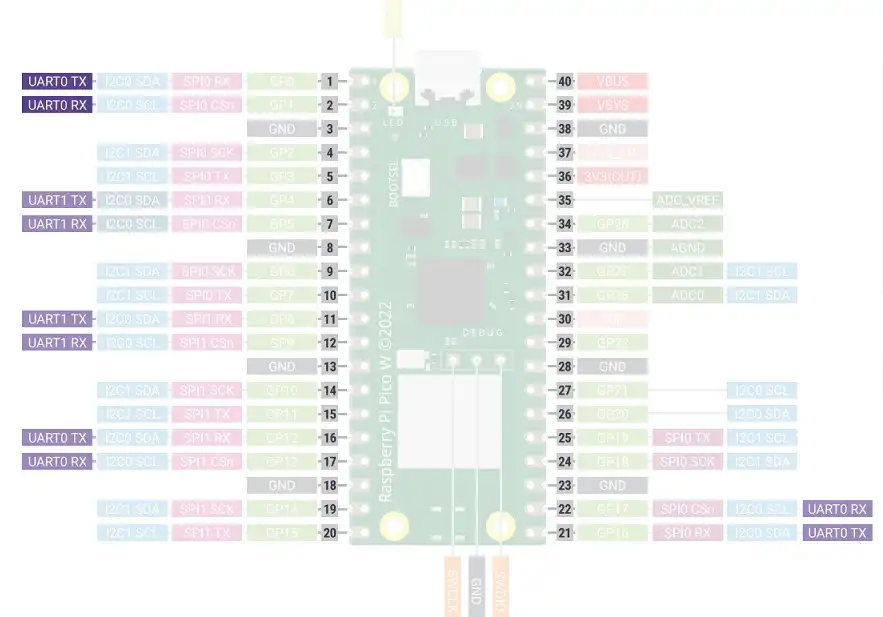
Pin Layout of Raspberry Pi Pico vs. Pico W
Both Raspberry Pi Pico & Pico W are identical in all aspects with regards to their GPIO pinout. Pico W is the successor to Pico. The hardware difference between the two boards is that Pico W supports Wi-Fi and Bluetooth while the earlier variant does not. Some minor differences such as debug pin layout, special pins, etc. will be discussed in this article.
Raspberry Pi Pico W Pinout Diagram
The following diagram shows the pinout of Raspberry Pi Pico W with the pin descriptions labeled.
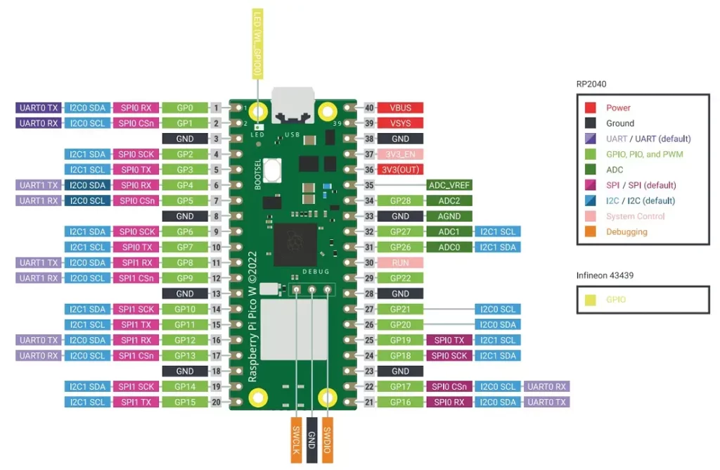
It might be helpful for you to open the pinout diagram in a new tab for easy reference while reading this article. Click here to open the Raspberry Pi Pico pinout image in a new tab in your browser.
The back of the board also has the pinout labeled. But if you solder pin headers to the board, the printed labels may be difficult to read.
Raspberry Pi Pico W Power Supply Pinout
Raspberry Pi Pico and Pico W include the following power pins:
- VBUS (PIN 40): This pin is connected to the micro-USB port and allows the Pico W to be powered through. It accepts a voltage range of 4.5V to 5.5V
- VSYS (PIN 39): Pin for main system input voltage. The input voltage can vary between 1.8V to 5.5V. This voltage is used by the onboard SMPS to generate 3.3V to power the RP2040 microcontroller and GPIOs.
- 3V3_EN (PIN 37): Used to enable the onboard SMPS for 3.3V. It is pulled high to the VSYS pin using a 100kΩ resistor.
- 3V3(OUT) (PIN 36): Outputs a regulated 3.3V voltage that can be used to power external components such as sensors. The datasheet recommends keeping the maximum load current from this pin to be under 300mA.
- GND: These pins provide the reference ground for the Pico W and connected devices. There are 8 GND pins available on the edge pinouts of Pico, all serving the same purpose.
- ADC_VREF (PIN 35): The ADC power supply & reference voltage pin that gets filtered 3.3V from the onboard SMPS.
- AGND (PIN 33): Ground reference pin for ADC.
- RUN (PIN 30): Enable pin for the RP2040 microcontroller. It is internally pulled up to 3.3V. It can be used to reset the Raspberry Pi Pico.
The VBUS voltage is fed through a Schottky diode to generate VSYS. If the USB port is not used, you can safely power Pico by connecting VSYS to a DC power source with a supply voltage in the range of ~1.8V to 5.5V. For example, you can use a single Li-ion battery (~3.7V) or 2/3 AA batteries in series to power your Pico.

Debug Pins
The following debug pins are available in Pico: SWDIO, GND, and SWCLK. Through these pins, we can access the Serial Wire Debug(SWD) interface in RP2040. Using SWD, we can reset, load, and run code on our microcontroller. Debug pins can help us find faults in code by executing the code line by line or by giving us information on the contents of internal registers.
On Raspberry Pi Pico, the debug pins are located towards the bottom of the board. In Pico W, the debug pins are below the RP2040 microcontroller.
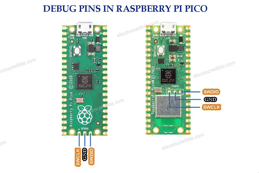
The word “DEBUG” written near the debug pins will help you to identify them easily.
Digital I/O Pinout
The Pico W board provides 26 General Purpose Input/Output (GPIO) pins that can be accessed using the header pins. The pins are 3.3V compatible. For input/output voltages that are more than 3.3V, one can use a logic level converter to shift the voltage to safe levels. The digital pins in Raspberry Pi Pico W are GPIO0 to GPIO22 and GPIO26 to GPIO28.
All GPIO pins can also be configured as interrupt pins for external input. Refer to our Raspberry Pi Pico Interrupts Guide to learn more.
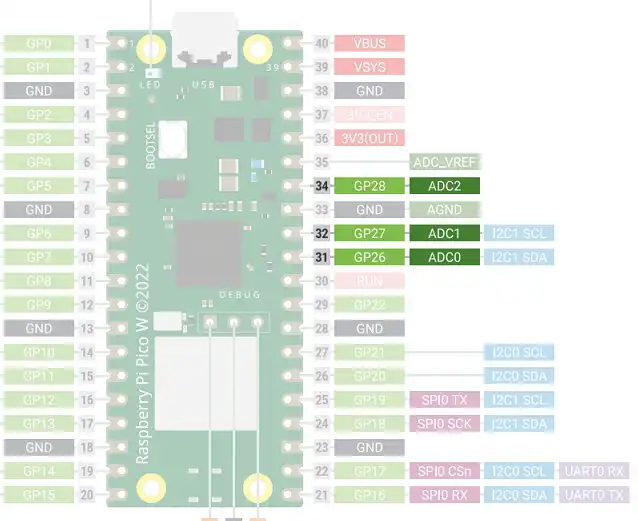
Analog Input/ ADC Pinout
Besides being digital I/O pins, GPIO26 to GPIO28 can also be used as ADC input pins to sense analog voltages. The ADC pins can read voltages between 0 V to 3.3 V.
A total of 5 ADC (Analog-to-Digital Converter) channels are available on the RP2040 microcontroller onboard Pico. An internal temperature sensor is coupled to one of the ADC channels. Through GPIO26, GPIO27, GPIO28, and GPIO29, respectively, you may access ADC0, ADC1, ADC2, and ADC3. However, GPIO29 is a special function pin and is not accessible through the GPIO pads.
The following table shows the GPIOs and the corresponding ADC channels we can access through the pinout.
| ADC Channel | GPIO |
| ADC 0 | GPIO 26 |
| ADC 1 | GPIO 27 |
| ADC 2 | GPIO 28 |
Refer to the pinout diagram of Raspberry Pi Pico below where the ADC pins are highlighted:
RPi Pico & Pico W PWM Pinout
The RP2040 in Raspberry Pi Pico has 8 identical slices of PWM block. Each slice can monitor the frequency or duty cycle of an input signal as well as produce two PWM output signals. So, there are 16 controllable PWM outputs. The PWM block may operate each of the 26 available GPIO pins onboard the Raspberry Pi Pico.
An in-depth article on the usage of PWM is described in our Raspberry Pi Pico PWM guide.
The pinout diagram below shows how the PWM pins are arranged.
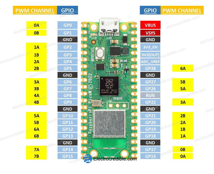
A PWM channel may control multiple GPIOs. The table below shows how the PWM channels relates to the GPIOs.
| PWM Channel | GPIO |
|---|---|
| 0A | GPIO 0, GPIO 16 |
| 0B | GPIO 1, GPIO 17 |
| 1A | GPIO 2, GPIO 18 |
| 1B | GPIO 3, GPIO 19 |
| 2A | GPIO 4, GPIO 20 |
| 2B | GPIO 5, GPIO 21 |
| 3A | GPIO 6, GPIO 22 |
| 3B | GPIO 7 |
| 4A | GPIO 8 |
| 4B | GPIO 9 |
| 5A | GPIO 10, GPIO 26 |
| 5B | GPIO 11, GPIO 27 |
| 6A | GPIO 12, GPIO 28 |
| 6B | GPIO 13 |
| 7A | GPIO 14 |
| 7B | GPIO 15 |
Raspberry Pi Pico & Pico W I2C Pinout
The RP2040 microcontroller in Raspberry Pi Pico has two dedicated hardware I2C controllers(I2C0 & I2C1). They are identical and can be independently controlled.
The diagram below shows the I2C Pinout of Pico & Pico W and the corresponding I2C controller connected to each pin.
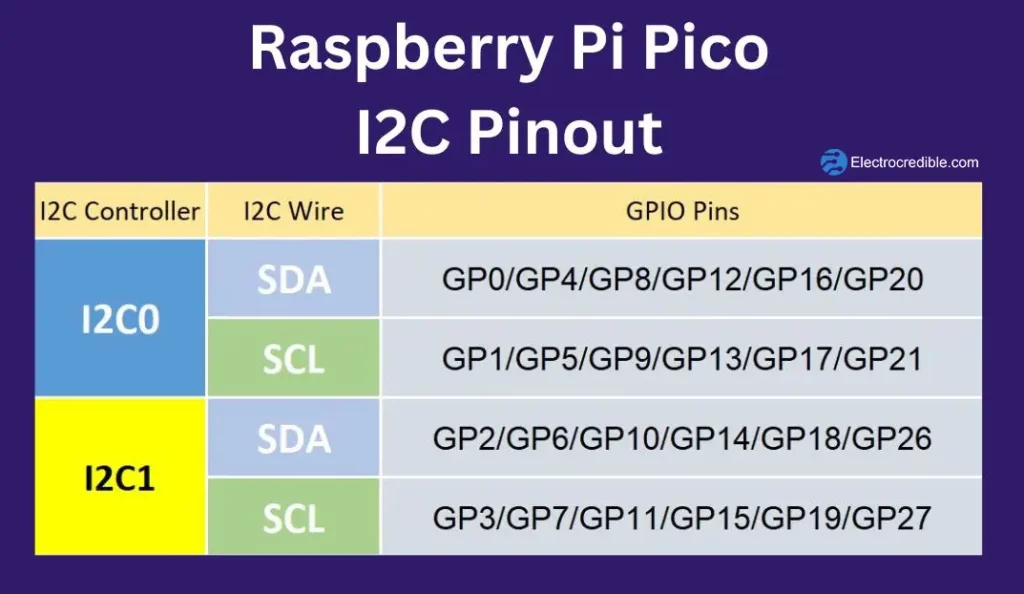
Apart from the dedicated hardware I2C controllers, we can also implement I2C in software. Also, the PIO(Programmable Input Output) in Raspberry Pi Pico can be configured to behave as an I2C interface.
Note that the I2C pins require pull-up resistors as explained in our Raspberry Pi Pico I2C Tutorial with examples. However, if you are interfacing Pico with a breakout board with in-built pull-up resistors (such as the BME280 environment sensor breakout board), you may not require external pull-up resistors.
UART Pinout
The RP2040 microcontroller in Raspberry Pi Pico has two UART peripherals, UART0 and UART1. The UART in RP2040 has the following features:
- Programmable Baud Rate generator.
- Programmable length of serial data bits(5 to 8 bits) and programmable length of stop bits(1 or 2 stop bits).
- Up to 32 bytes can be stored separately in both the transmit and receive modes of the UART.
- Interrupts are triggered based on transmission & reception of data, modem status, communication error, or reception timeout.
The image below demonstrates the Raspberry Pi Pico & Pico W pinout which can be used for serial communication via UART.
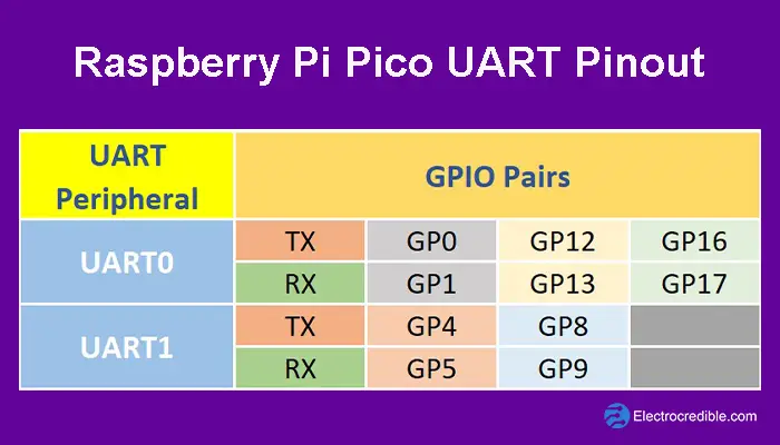
The pinout diagram below shows the pins for UART highlighted.
For more details, refer to our Raspberry Pi Pico serial communication guide.
Raspberry Pi Pico SPI Pinout
The Pico has 2 SPI peripherals with a programmable clock rate and programmable data size. The two SPI peripherals are named as SPIO & SPI1. Here is a pinout diagram with the SPI pins highlighted.
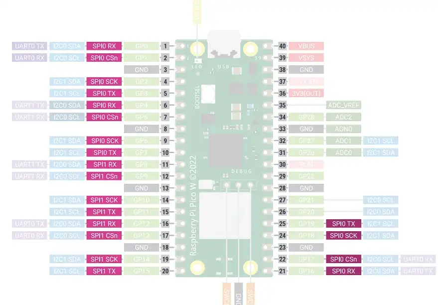
The SPI Pin names can be interpreted as:
- SPI SCK: Pin for clock signal to synchronize serial data.
- SPI RX: SPI pin for transmitting data.
- SPI TX: SPI pin for receiving data.
- SPI CSn: Chip Select signal pin.
SPI is used to read a temperature sensor in our article: Thermocouple interfacing with Raspberry Pi Pico using MicroPython.
Special Function Pins
Some pins are used for some special functions in Pico boards. They are not available for user interfacing through the DIP pins on the left and right edges of the board.
The following pins are for internal board functions in RPi Pico:
| Pin | Function |
|---|---|
| GPIO23 | Controls the on-board SMPS power save pin. |
| GPIO24 | Senses voltage at VBUS pin – high if VBUS is present, else low. |
| GPIO25 | Connected to onboard LED. |
| GPIO29 | Used in ADC mode (ADC3) to measure VSYS/3. |
The special function pins in RPi Pico W are:
| Pin | Function |
|---|---|
| GPIO23 | Output(OP) pin for wireless power-on signal. |
| GPIO24 | OP/IP pin for wireless SPI data/IRQ. |
| GPIO25 | OP wireless SPI CS pin – when high it also enables GPIO29 ADC pin to read VSYS. |
| GPIO29 | OP/IP wireless SPI CLK/ADC mode (ADC3) to measure VSYS/3. |
The GPIOs of the Infineon CYW4343 wireless chip onboard Pico W also provide some onboard functions:
| Pin | Function |
|---|---|
| WL_GPIO0 | Connects to the onboard LED. |
| WL_GPIO1 | Controls the on-board SMPS power save pin. |
| WL_GPIO2 | Senses voltage at VBUS pin – high if VBUS is present, else low. |
Outro
In this guide, we learned about the pinout of Raspberry Pi Pico and Pico W and how we can use them. The pinout is your indispensable guide to unlocking the vast potential of this versatile microcontroller board. It may be helpful to bookmark this article for easy reference later. Thank you for reading.
Leave a Reply