This article will guide you to use Pulse Width Modulation(PWM) in Raspberry Pi Pico and Raspberry Pi Pico W. First, we shall briefly discuss how PWM can be used to dim an LED. Then we will learn to interface a potentiometer to control the brightness of the LED. The analog value of the potentiometer will be read using the Analog-to-digital converter(ADC) and the LED brightness will change according to the ADC value.
Components Required & Setup
- A Raspberry Pi Pico or Pico W.
- An LED and a current limiting resistor.
- Breadboard and connecting wires.
Your Raspberry Pi Pico needs to be preloaded with a MicroPython UF2 file to program it in MicroPython. You can read our getting started guide for Raspberry Pi Pico where we show all the steps required to start programming Raspberry Pi Pico using MicroPython.
What is Pulse Width Modulation (PWM)?
PWM is a modulation technique using which the width of waves in a pulse train can be varied. It has a wide variety of applications such as:
- Generation of analog voltages using a digital signal.
- Speed control of electric motors.
- Telecommunications.
- Audio synthesis and amplification.
Duty Cycle, frequency, and period are three notable parameters of a PWM signal. Frequency relates to the number of times a PWM signal switches between ON and OFF states per second. In the case of LVTTL(Low voltage Transistor-Transistor Logic), the ON/HIGH state is 3.3 Volts and the OFF/LOW state is 0 Volts for most applications. As Raspberry Pi Pico features RP2040 which operates at LVTTL levels, we will use these standard voltages for PWM demonstration.
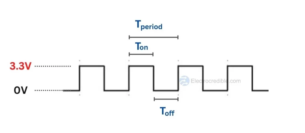
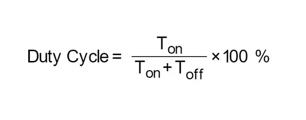
A PWM signal resembles a square wave where the signal is ON for some duration and then it is OFF for some duration. The sum of ON time and OFF time is the period of a PWM wave. The Duty Cycle of the PWM wave is the percentage of time the signal remains at the ON state relative to the period of the PWM signal.
By varying the duty cycle, we can vary the average voltage supplied to an electronic component such as an LED. The more the duty cycle of a PWM signal, the more voltage will be delivered to a load.
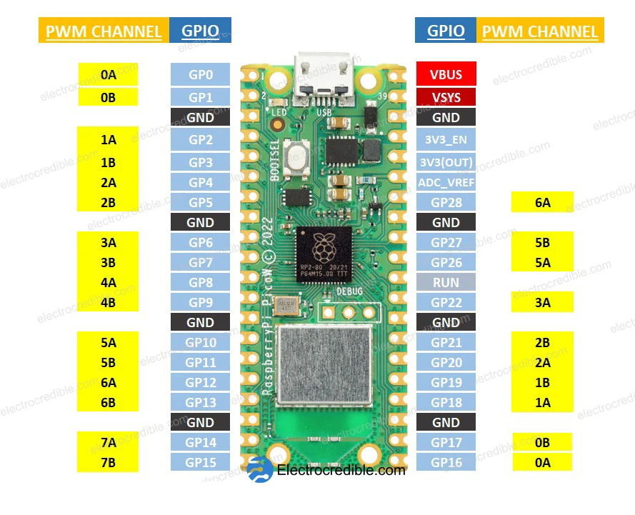
Raspberry Pi Pico PWM Pinout
The RP2040 in Raspberry Pi Pico has 8 identical slices of PWM block. Each slice can monitor the frequency or duty cycle of an input signal as well as produce two PWM output signals. So there are 16 controllable PWM outputs. The PWM block may operate each of the 26 available GPIO pins onboard the Raspberry Pi Pico.

Raspberry Pi Pico PWM Example 1: Fading LED Effect
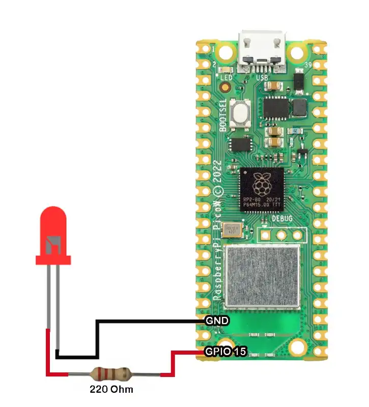
The breathing LED or fading LED effect will pulse an LED in the rhythmic pattern of human breathing. Connect an LED on PIN 15 of Raspberry Pi Pico which will be used for the PWM pinout.
Here is the MicroPython code for the fading LED effect:
from machine import Pin, PWM
import time

led_pwm = PWM(Pin(15))
led_pwm.freq(1000)

def fade_led():
    for duty_cycle in range(0, 65535, 256):  # 16-bit PWM resolution
        led_pwm.duty_u16(duty_cycle)
        time.sleep_ms(10)  # Adjust the sleep time for the desired fading speed

    for duty_cycle in range(65535, 0, -256):
        led_pwm.duty_u16(duty_cycle)
        time.sleep_ms(10)  # Adjust the sleep time for the desired fading speed

while True:
    fade_led()Code language: Python (python)
Upon running the code, the LED connected to PIN 15 must pulse with a breathing effect.
Code Explanation
Import the Pin and PWM classes from the machine module. These classes are used for interacting with hardware pins and controlling PWM signals.
from machine import Pin, PWMCode language: JavaScript (javascript)Import the time module, which is commonly used for introducing delays in the program.
import timeCode language: JavaScript (javascript)The next line initializes a PWM object named led_pwm by assigning it to GPIO pin 15.
led_pwm = PWM(Pin(15))Sets the frequency of the PWM signal to 1000 Hz (1 kHz). The frequency determines how quickly the PWM signal cycles
led_pwm.freq(1000)Code language: CSS (css)Define a function named fade_led. This function will control the fading effect of the LED.
def fade_led()Initiate a for loop where duty_cycle takes values from 0 to 65535 (16-bit PWM resolution) in increments of 256. This loop is for increasing the duty cycle, thereby increasing the brightness of the LED.
for duty_cycle in range(0, 65535, 256):Set the duty cycle of the PWM signal to the current value of duty_cycle. The duty cycle represents the fraction of time the PWM signal is high compared to the total period.
led_pwm.duty_u16(duty_cycle)Code language: CSS (css)Next, introduce a delay of 10 milliseconds to control the speed of the fading effect. You can adjust this value to change the fading speed.
time.sleep_ms(10)Code language: CSS (css)The next for loop (for duty_cycle in range(65535, 0, -256):) and the following lines have the same purpose as the previous loop but in reverse. It decreases the duty cycle, creating a fading-out effect.
In the while loop, we call the fade_led function defined earlier, causing the LED to continuously fade in and out.
PWM Example 2: Control LED Brightness using Potentiometer
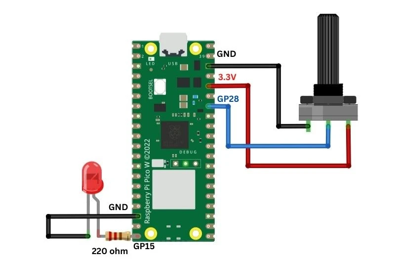
Connect an LED, a 220ohm resistor, and a 10K potentiometer as shown below. The values of these components can vary within practical limits. Remember to connect the LED with the correct polarity.
Recommended article: How to interface a potentiometer with Raspberry Pi Pico. Since this article is primarily focused on controlling the brightness of an LED, readers can visit the linked article to learn more about interfacing potentiometers with Pi Pico. The article also explains the Analog to Digital(ADC) converter in Raspberry Pi Pico.
Instead of using an external LED, you can also use the onboard LED in Raspberry Pi Pico.
MicroPython Code for PWM Control of LED using Potentiometer
Let us write a simple MicroPython script to control LED brightness using Raspberry Pi Pico W.
from machine import Pin, PWM, ADC
adc = machine.ADC(28)
pwm0 = PWM(Pin(15))
pwm0.freq(1000)
while True:
    digital_value = adc.read_u16()
    pwm0.duty_u16(digital_value)      # set duty cycle, range 0-65535Code language: Python (python)
When you run the code, you should be able to vary the brightness of the LED by rotating the potentiometer.
Code Explanation.
We first import the necessary libraries and classes required for the code to work. The Pin class is used to send/read data from the GPIOs, the PWM class will be used for pulse width modulation using the GPIOs and the ADC class will help us to read analog values from a potentiometer.
from machine import Pin, PWM, ADC
import timeCode language: JavaScript (javascript)
GPIO 28 is set as an ADC input pin. You can also set it as any other pin available for ADC in Raspberry Pi Pico.
adc = machine.ADC(28)Next, we set GPIO 15 as the PWM output pin and set the frequency of the PWM as 1Khz. An object pwm0 is initiated with these parameters.
pwm0 = PWM(Pin(15))
pwm0.freq(1000)
The code inside the while loop gets the reading from ADC and sets the duty cycle of PWM. The method adc.read_u16() returns ADC values in the 0 to 65535 (2^16-1) range. Raspberry Pi Pico can set duty cycle in the range of 0 to 65535, where 0 will give a PWM signal of 0% duty cycle and 65535 will output a PWM signal of 100% duty cycle. The method pwm0.duty_u16(digital_value) will set the duty cycle of the PWM according to the value read by the ADC.
digital_value = adc.read_u16()
pwm0.duty_u16(digital_value)
MicroPython Methods for PWM
Apart from the code we discussed above, here are some other useful MicroPython PWM methods, with a PWM object pwm0:
- pwm0.frequency: get the current PWM frequency.
- pwm0.duty_u16(): get the current duty cycle of PWM.
- pwm0.deinit(): turn off PWM for the pin.
Leave a Reply