This tutorial explains how to interface the DS3231 RTC module with Raspberry Pi Pico using MicroPython & Arduino code. The wiring diagram, libraries required for interfacing, and working of the components are explained in-depth.
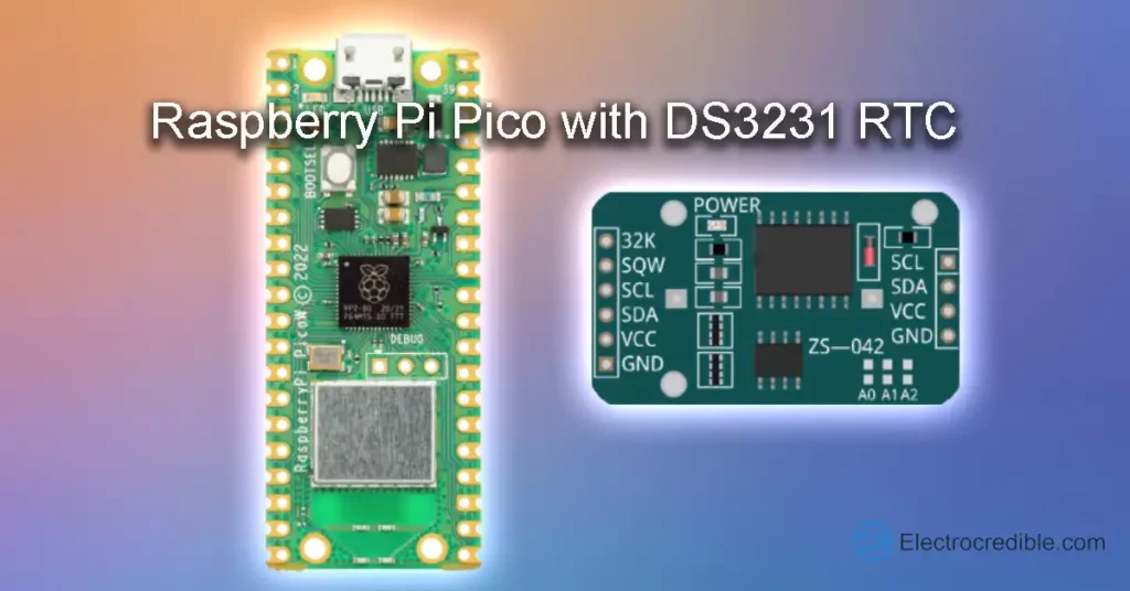
A real-time clock (RTC) is a dedicated integrated circuit used to measure time. These circuits consume very low power and can be powered using batteries such as coin cells. DS3231 is a popular RTC IC used in embedded systems. It is commonly available as a module (ZS-042) with onboard EEPROM and a battery holder.
Overview of DS3231 RTC Module
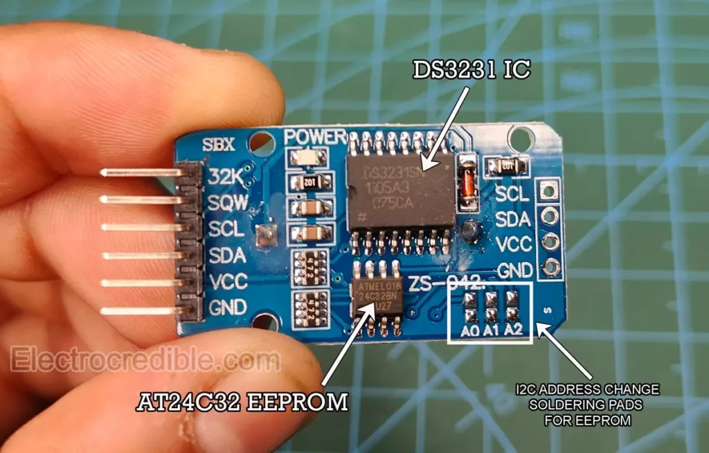
The DS3231 (ZS-042) module features the DS3231 IC and an AT24C32 EEPROM. Both of these ICs can communicate via I2C. The EEPROM is not related to RTC functions but can act as a non-volatile memory for data logging. Onboard soldering pads help to change the address of the EEPROM IC, in case we want to use multiple EEPROM on the same I2C bus. There is a button cell holder on the other side. This module is an all-in-one solution to build data loggers by interfacing with a microcontroller.
Specifications of the DS3231 Module
- Operating Voltage: 2.3 to 5.5V.
- Battery backup: 2.3 to 5.5V. A 3V coin cell is commonly used (such as the CR2032 battery).
- Maximum active supply current: 300 µA.
- Real-time clock counts seconds, minutes, hours, date of the month, month, day of the week, and year, with leap-year compensation valid up to the year 2100.
- Accuracy: ±2ppm from 0°C to +40°C, ±3.5ppm from -40°C to +85°C.
- Fast (400kHz) I2C Interface.
- It is driven by a 32kHz temperature-compensated crystal oscillator (TCXO). The TCXO helps to maintain the RTC within ±2 minutes per year accuracy from -40°C to +85°C.
ⓘ DS1302 is a similar IC that comes at a lower cost than DS3231 but has some shortcomings such as lower accuracy, absence of I2C, and no built-in temperature compensation. You can read about it in our article – Interfacing Raspberry Pi Pico with DS1302.
Powering the Module
The DS32321 RTC module contains a coil cell holder for a rechargeable battery. If we want to power the module using an external supply and non-rechargeable battery (e.g. CR2032) we must do one of the following:
- Remove the battery from the holder while external power is fed through the VCC pin.
- Remove or desolder the onboard resistor near the diode(shown in red). The resistor and diode are used for charging a Lithium-ion coin cell(LIR2032).
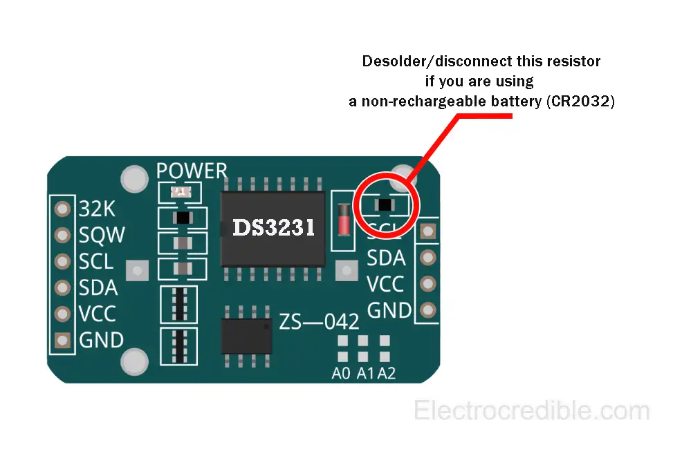
⚠ Using a non-rechargeable battery without following one of these steps may damage your battery.
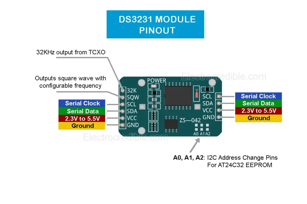
DS3231 Pinout
The DS3231 module provides I2C pins on both sides of the module, which will be convenient in case we want to daisy-chain other I2C devices to the same bus. Below is the pinout of the ZSS-042 DS3231 Module:
Detailed pin description:
| DS3231 Module (ZS-042) Pins | Pin Description |
| 32K | Output a 32KHz wave from the internal TCXO |
| SQW | Square wave output with configurable frequency between 1Hz to 8.192kHz. |
| SCL | Serial Clock pin for I2C interface |
| SDA | Serial Data pin for I2C interface |
| VCC | 2.3V to 5.5V supply voltage |
| GND | Ground pin |
RTC DS3231 with Raspberry Pi Pico: Interface Using MicroPython
To use MicroPython code on Raspberry Pi Pico or Pico W, we first need to flash MicroPython firmware on Pico. You can read our getting started guide for Raspberry Pi Pico where we show all the steps required to start programming Raspberry Pi Pico & Pico W.
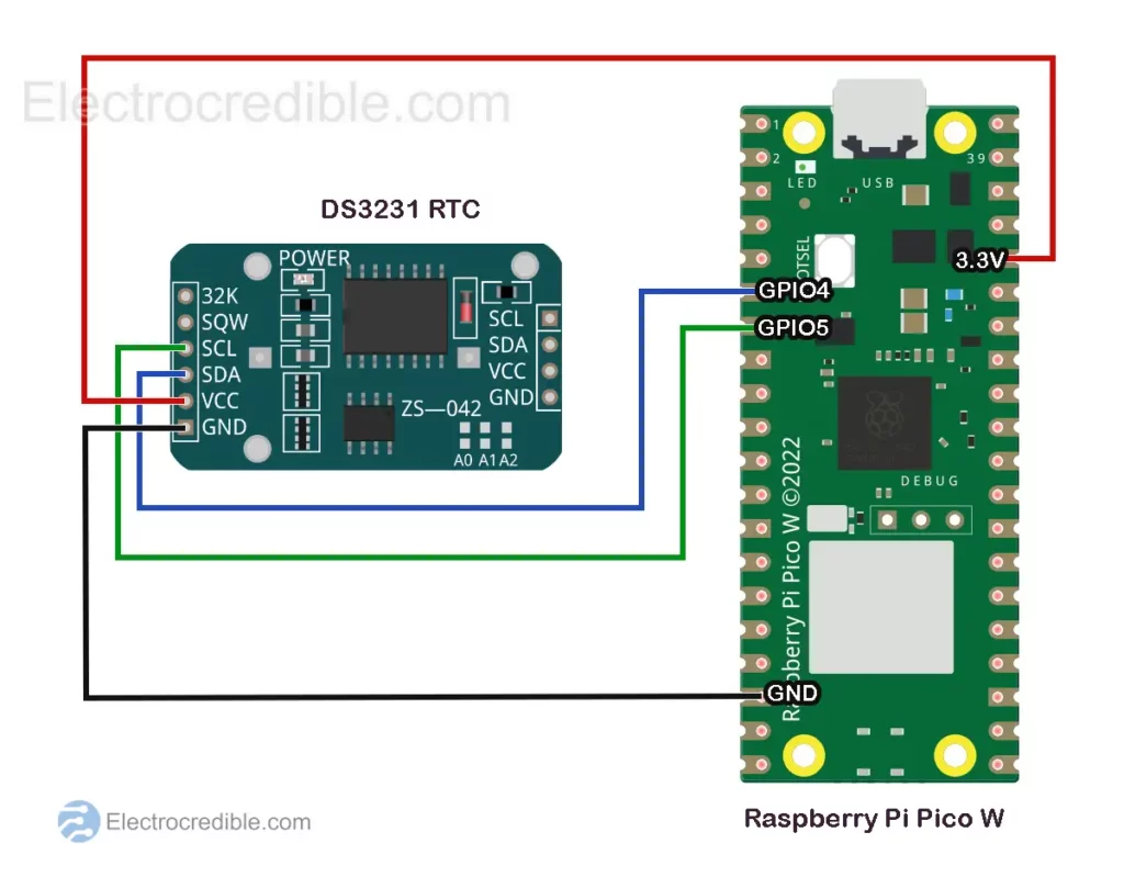
Wiring
We shall use GPIO 4 in Raspberry Pi Pico W as the SDA pin and GPIO 5 as the SCL pin to interface with the DS3231 RTC module.
After wiring, it is recommended to scan for I2C devices and see if DS3231 is detected. Here is the code to scan for devices connected to the I2C bus:
# Import the machine module for hardware access
import machine
# Initialize the SDA (Serial Data Line) pin for I2C communication
sdaPIN = machine.Pin(4)
# Initialize the SCL (Serial Clock Line) pin for I2C communication
sclPIN = machine.Pin(5)
# Initialize the I2C interface with the specified pins and frequency
i2c = machine.I2C(0, sda=sdaPIN, scl=sclPIN, freq=400000)
# Scan for devices connected to the I2C bus
devices = i2c.scan()
# Check if any devices are found
if len(devices) == 0:
# If no devices are found, print a message
print("No I2C devices found!")
else:
# If devices are found, print the number of devices found
print('I2C devices found:', len(devices))
# Iterate through each device found and print its hexadecimal address
for device in devices:
print("Hexadecimal address:", hex(device))
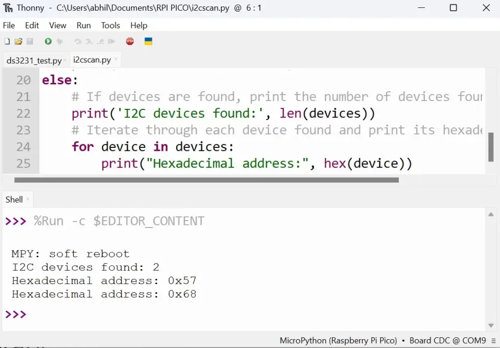
Code language: PHP (php)The following screenshot in Thonny IDE shows the hexadecimal addresses of the I2C devices. The I2C address of DS3231 is detected as 0x68 and the I2C address of the EEPROM is 0x57.
DS3231 MicroPython Library
DS3231 requires various commands to read and retrieve data from the EEPROM, read/write the alarm registers, and other functional registers. Thankfully, various libraries help to easily interface it with microcontrollers. Here, we shall use the DS3231 MicroPython library by Peter Hinch. The library has methods for dateTime and alarm. Only the dateTime set feature will be discussed here.
Copy and paste the following DS3231 MicroPython library code and save it to Raspberry Pi Pico as ds3231.py.
# Author: Peter Hinch
# Copyright Peter Hinch 2023 Released under the MIT license.


import time
import machine

_ADDR = const(104)

EVERY_SECOND = 0x0F  # Exported flags
EVERY_MINUTE = 0x0E
EVERY_HOUR = 0x0C
EVERY_DAY = 0x80
EVERY_WEEK = 0x40
EVERY_MONTH = 0

try:
    rtc = machine.RTC()
except:
    print("Warning: machine module does not support the RTC.")
    rtc = None


class Alarm:
    def __init__(self, device, n):
        self._device = device
        self._i2c = device.ds3231
        self.alno = n  # Alarm no.
        self.offs = 7 if self.alno == 1 else 0x0B  # Offset into address map
        self.mask = 0

    def _reg(self, offs : int, buf = bytearray(1)) -> int:  # Read a register
        self._i2c.readfrom_mem_into(_ADDR, offs, buf)
        return buf[0]

    def enable(self, run):
        flags = self._reg(0x0E) | 4  # Disable square wave
        flags = (flags | self.alno) if run else (flags & ~self.alno & 0xFF)
        self._i2c.writeto_mem(_ADDR, 0x0E, flags.to_bytes(1, "little"))

    def __call__(self):  # Return True if alarm is set
        return bool(self._reg(0x0F) & self.alno)

    def clear(self):
        flags = (self._reg(0x0F) & ~self.alno) & 0xFF
        self._i2c.writeto_mem(_ADDR, 0x0F, flags.to_bytes(1, "little"))

    def set(self, when, day=0, hr=0, min=0, sec=0):
        if when not in (0x0F, 0x0E, 0x0C, 0x80, 0x40, 0):
            raise ValueError("Invalid alarm specifier.")
        self.mask = when
        if when == EVERY_WEEK:
            day += 1  # Setting a day of week
        self._device.set_time((0, 0, day, hr, min, sec, 0, 0), self)
        self.enable(True)


class DS3231:
    def __init__(self, i2c):
        self.ds3231 = i2c
        self.alarm1 = Alarm(self, 1)
        self.alarm2 = Alarm(self, 2)
        if _ADDR not in self.ds3231.scan():
            raise RuntimeError(f"DS3231 not found on I2C bus at {_ADDR}")

    def get_time(self, data=bytearray(7)):
        def bcd2dec(bcd):  # Strip MSB
            return ((bcd & 0x70) >> 4) * 10 + (bcd & 0x0F)

        self.ds3231.readfrom_mem_into(_ADDR, 0, data)
        ss, mm, hh, wday, DD, MM, YY = [bcd2dec(x) for x in data]
        YY += 2000
        # Time from DS3231 in time.localtime() format (less yday)
        result = YY, MM, DD, hh, mm, ss, wday - 1, 0
        return result

    # Output time or alarm data to device
    # args: tt A datetime tuple. If absent uses localtime.
    # alarm: An Alarm instance or None if setting time
    def set_time(self, tt=None, alarm=None):
        # Given BCD value return a binary byte. Modifier:
        # Set MSB if any of bit(1..4) or bit 7 set, set b6 if mod[6]
        def gbyte(dec, mod=0):
            tens, units = divmod(dec, 10)
            n = (tens << 4) + units
            n |= 0x80 if mod & 0x0F else mod & 0xC0
            return n.to_bytes(1, "little")

        YY, MM, mday, hh, mm, ss, wday, yday = time.localtime() if tt is None else tt
        mask = 0 if alarm is None else alarm.mask
        offs = 0 if alarm is None else alarm.offs
        if alarm is None or alarm.alno == 1:  # Has a seconds register
            self.ds3231.writeto_mem(_ADDR, offs, gbyte(ss, mask & 1))
            offs += 1
        self.ds3231.writeto_mem(_ADDR, offs, gbyte(mm, mask & 2))
        offs += 1
        self.ds3231.writeto_mem(_ADDR, offs, gbyte(hh, mask & 4))  # Sets to 24hr mode
        offs += 1
        if alarm is not None:  # Setting an alarm - mask holds MS 2 bits
            self.ds3231.writeto_mem(_ADDR, offs, gbyte(mday, mask))
        else:  # Setting time
            self.ds3231.writeto_mem(_ADDR, offs, gbyte(wday + 1))  # 1 == Monday, 7 == Sunday
            offs += 1
            self.ds3231.writeto_mem(_ADDR, offs, gbyte(mday))  # Day of month
            offs += 1
            self.ds3231.writeto_mem(_ADDR, offs, gbyte(MM, 0x80))  # Century bit (>Y2K)
            offs += 1
            self.ds3231.writeto_mem(_ADDR, offs, gbyte(YY - 2000))

    def temperature(self):
        def twos_complement(input_value: int, num_bits: int) -> int:
            mask = 2 ** (num_bits - 1)
            return -(input_value & mask) + (input_value & ~mask)

        t = self.ds3231.readfrom_mem(_ADDR, 0x11, 2)
        i = t[0] << 8 | t[1]
        return twos_complement(i >> 6, 10) * 0.25

    def __str__(self, buf=bytearray(0x13)):  # Debug dump of device registers
        self.ds3231.readfrom_mem_into(_ADDR, 0, buf)
        s = ""
        for n, v in enumerate(buf):
            s = f"{s}0x{n:02x} 0x{v:02x} {v >> 4:04b} {v & 0xF :04b}\n"
            if not (n + 1) % 4:
                s = f"{s}\n"
        return s
MicroPython Code for DS3231
Let us first save the DateTime to the RTC. The code below will set the RTC to the system time using the method ds.set_time(). DateTime tuples are used to set and read time values. These tuples are of the form: (year, month, day, hour, minute, second, weekday, yearday).
# Import necessary modules
from machine import I2C, Pin
from ds3231 import *
import time

# Define the pins for I2C communication
sda_pin=Pin(4)
scl_pin=Pin(5)

# Initialize the I2C interface with the specified pins
i2c = I2C(0, scl=scl_pin, sda=sda_pin)
time.sleep(0.5)

# Create an instance of the DS3231 class for interfacing with the DS3231 RTC
ds = DS3231(i2c)

# Set the DS3231 RTC to current system time
ds.set_time()Code language: PHP (php)
Now that the DateTime data is saved, we can print it using the following script:
from machine import I2C, Pin
from ds3231 import *
import time

sda_pin=Pin(21)
scl_pin=Pin(22)

i2c = I2C(0, scl=scl_pin, sda=sda_pin)
time.sleep(0.5)

ds = DS3231(i2c)

# Print the current date in the format: month/day/year
print( "Date={}/{}/{}" .format(ds.get_time()[1], ds.get_time()[2],ds.get_time()[0]) )

# Print the current time in the format: hours:minutes:seconds
print( "Time={}:{}:{}" .format(ds.get_time()[3], ds.get_time()[4],ds.get_time()[5]) )Code language: PHP (php)
Steps to Upload Code
The steps to upload MicroPython code are explained using Thonny IDE.
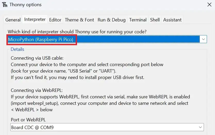
1. With all connections done according to the schematic, connect the Pico to your computer using a USB cable. Open Thonny IDE and set the interpreter to use MicroPython on Raspberry Pi Pico.
2. Go to File>New in Thonny IDE to create a new project.
3. Paste the code into a new project.
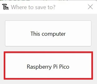
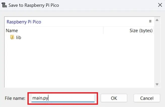
4. Click on File>Save as and select the save location as Raspberry Pi Pico.
5. Name the library code ds3231.py and the main script as main.py or any other filename with a “.py” filename extension.
6. Run the code by clicking the Run icon or by pressing the F5 key.

Demonstration
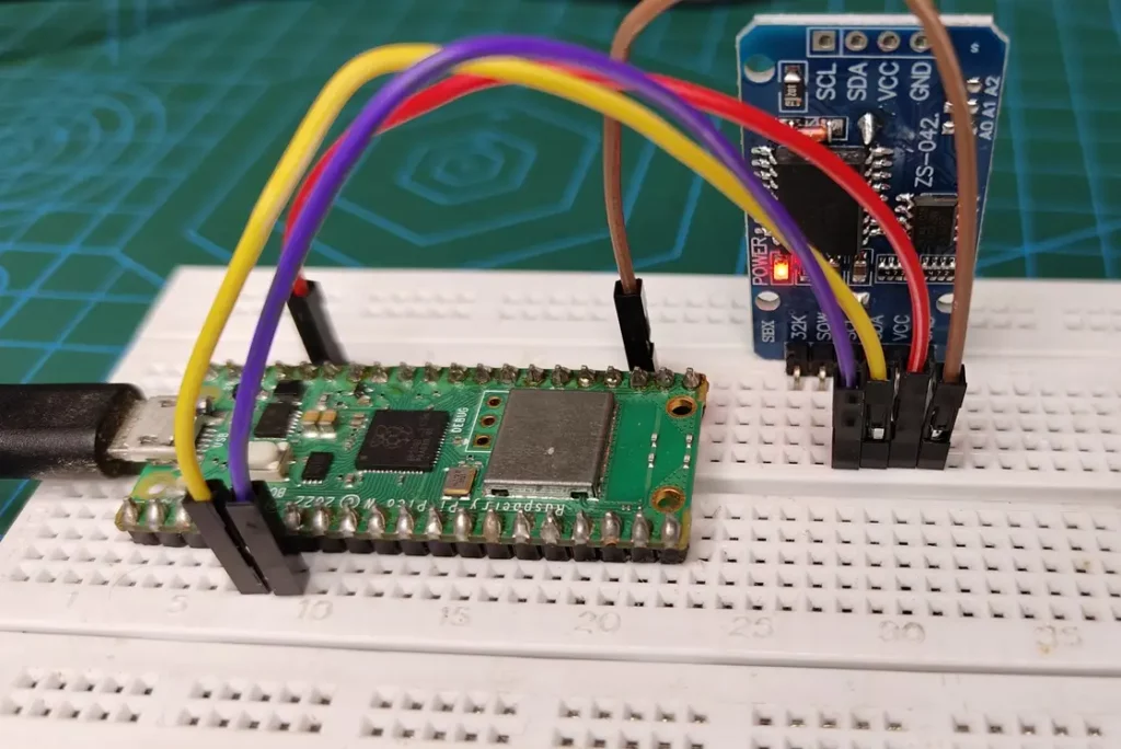
Here is the circuit assembled on a breadboard with 4 connecting wires:
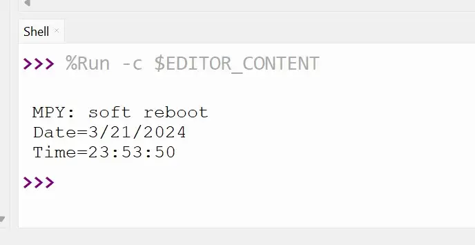
The screenshot below shows the output in the shell of Thonny IDE when the script to get the time was run.
Interface DS3231 with Raspberry Pi Pico using Arduino Code
To program Raspberry Pi Pico with Arduino, we first set up Pico for use with Arduino IDE. It involves uploading code while holding the BOOTSEL button the first time we upload code using Arduino IDE. Read our guide – How to Program Raspberry Pi Pico using Arduino IDE 2.0 to learn more.
In Raspberry Pi Pico and Pico W, the default I2C pins are GPIO4 for SDA and GPIO5 for SCL. So the wiring is the same as shown for the MicroPython example earlier.
Arduino Library for DS3231 RTC
We shall use the RTClib by Adafruit, which helps in interfacing with the Ds3231 RTC.
The steps to install the library in Arduino IDE 2.0 are explained below.
1. In Arduino IDE, go to Sketch>Include Library>Manager Libraries.
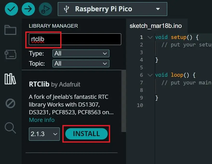
2. Search for “RTClib” and install it from the search results.
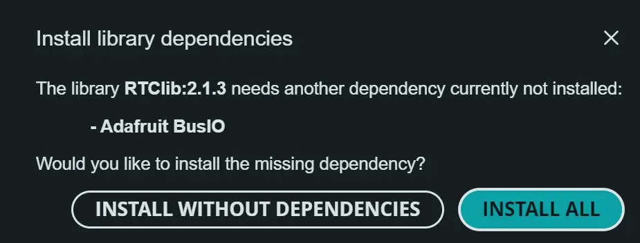
3. If the option to install dependencies appears, click on Install All.
Arduino Code
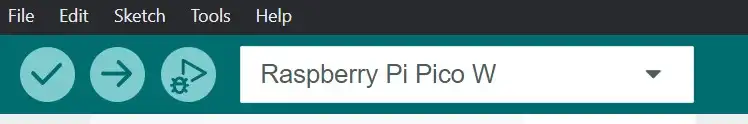
After setting up the library, set the Arduino IDE to use the Raspberry Pi Pico board and also select the correct port.
Arduino code to set the RTC:
#include "RTClib.h"

RTC_DS3231 rtc;

char daysOfTheWeek[7][12] = {"Sunday", "Monday", "Tuesday", "Wednesday", "Thursday", "Friday", "Saturday"};

void setup () {
  Serial.begin(57600);

  if (! rtc.begin()) {
    Serial.println("Couldn't find RTC");
    Serial.flush();
    while (1) delay(10);
  }

  rtc.adjust(DateTime(F(__DATE__), F(__TIME__)));

}

void loop () {

}Code language: PHP (php)
Arduino code to print RTC data:
#include "RTClib.h"
RTC_DS3231 rtc;
char daysOfTheWeek[7][12] = {"Sunday", "Monday", "Tuesday", "Wednesday", "Thursday", "Friday", "Saturday"};
void setup () {
Serial.begin(57600);
if (! rtc.begin()) {
Serial.println("Couldn't find RTC");
Serial.flush();
while (1) delay(10);
}
}
void loop () {
DateTime now = rtc.now();
Serial.print(now.year(), DEC);
Serial.print('/');
Serial.print(now.month(), DEC);
Serial.print('/');
Serial.print(now.day(), DEC);
Serial.print(" (");
Serial.print(daysOfTheWeek[now.dayOfTheWeek()]);
Serial.print(") ");
Serial.print(now.hour(), DEC);
Serial.print(':');
Serial.print(now.minute(), DEC);
Serial.print(':');
Serial.print(now.second(), DEC);
Serial.println();
delay(3000);
}
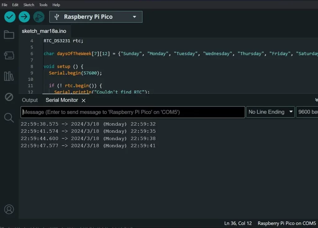
Code language: PHP (php)Demonstration
The screenshot below shows the output from DS3231 RTC in Serial Monitor of Arduino IDE 2.0.

Conclusion
In this guide, we learned how to interface the DS3231 module with Raspberry Pi Pico W using MicroPython and Arduino code. Using this information, we can build various projects such as data loggers, DIY clocks, etc.
Leave a Reply