In this article, you will learn to use the I2C interface in Raspberry Pi Pico & Pico W. I2C is a widely used communication interface in embedded systems for communication between microcontrollers and external peripherals. As an example, we will learn to interface a display using I2C.
Here, we also discuss how to connect multiple I2C devices to Raspberry Pi Pico W.
What is I2C? A Brief Overview
I2C is a Serial Communication Protocol invented by Phillips. I2C is commonly referred to as I2C or IIC. This system of communication uses two bidirectional lines, namely SDA(Serial Data) and SCL(Serial Clock). The lines are usually pulled up to the system voltage using resistors. 10-kiloohm resistors are commonly used to pull the data and clock lines to system voltage(usually 3.3V or 5V).
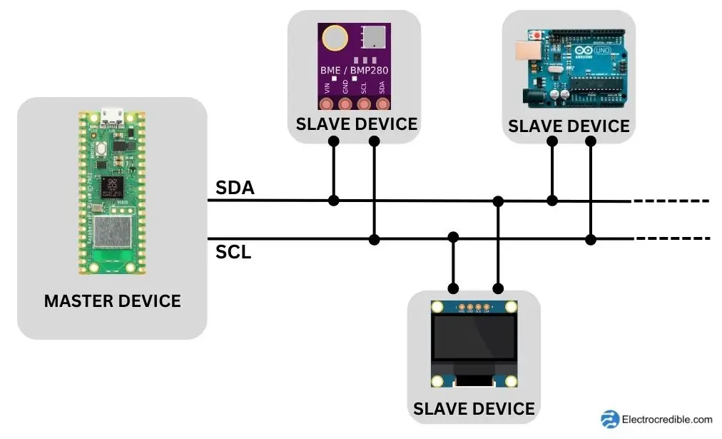
The I2C bus identifies peripherals(nodes) with 7-bit addresses. Each node can act as either a master or a slave while communicating. The master device usually generates the clock signal in the SCL line. Multiple slave devices can communicate with a single master device.
I2C shares many similarities with TWI(Two-Wire Protocol). To avoid legal issues, the term TWI is used by some vendors. There are a few differences between the two protocols, for example, TWI does not use a START byte in its data packet. In most situations, they can be used interchangeably.
Raspberry Pi Pico I2C Pinout & Specifications
Raspberry Pi Pico / Pico W is built upon the 32-bit dual ARM Cortex-M0+ microcontroller RP2040 microcontroller. It has two dedicated hardware I2C controllers(I2C0 & I2C1) that are identical and can be independently controlled. The I2C controller can act as both master and slave, with the master mode being the default. However, it cannot behave as a master and slave at the same time.
The I2C in RPi Pico can work in three data transfer modes:
- standard mode (with data rates from 0 to 100kbps),
- fast mode (with data rates less than or equal to 400kbps),
- and fast mode plus (with data rates less than or equal to 1000kbps).
Devices in fast mode are downward compatible. For instance, with the 0 to 100kbps I2C bus system, fast-mode devices can connect with standard-mode devices. However, because they cannot keep up with the faster transmission rate and would experience unpredictable states, standard mode devices are not upward compatible and shouldn’t be included in a fast-mode I2C bus system.
Take a look at the pinout of Raspberry Pi Pico W below. The pins marked as SDA and SCL can be used for I2C communication.
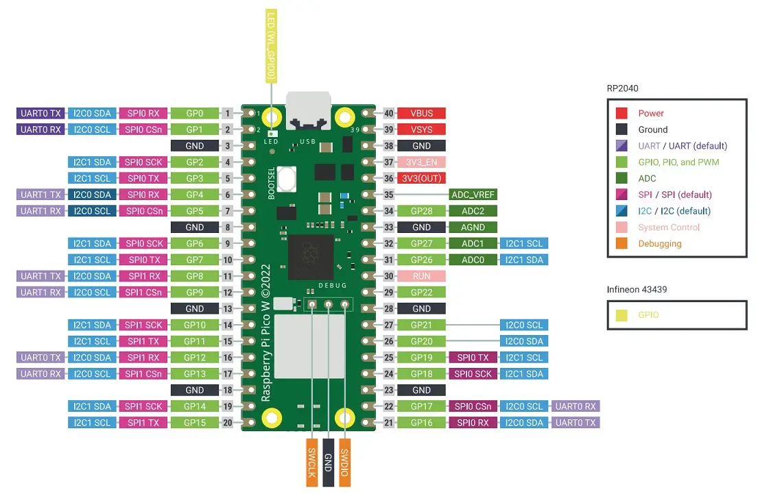
The default I2C pins in Raspberry Pi Pico are GPIO 4 for SDA and GPIO 5 for SCL. Both of these pins are a part of the I2C0 hardware I2C controller.
Apart from the dedicated hardware I2C controllers, we can also implement I2C in software. Also, the PIO(Programmable Input Output) in Raspberry Pi Pico can be configured to behave as an I2C interface.
Also Read: Arduino vs MicroPython vs CircuitPython: Which One Will You Choose?
Raspberry Pi Pico I2C Example using an OLED Display
To proceed, you need to have a Raspberry Pi Pico W with a MicroPython UF2 file loaded. If your Pi Pico is not running MicroPython, you can follow our guide Getting Started with Pico W & MicroPython. After the UF2 file is in place, you can begin accessing the I2C hardware in Pi Pico using simple functions in the code.
Connect your Pi Pico to an OLED display as shown in the diagram below. If you don’t have an OLED display, you can find links to other projects using I2C at the end of this article. The OLED display used is 128×64 pixels in dimensions and consists of an SSD1306 controller.
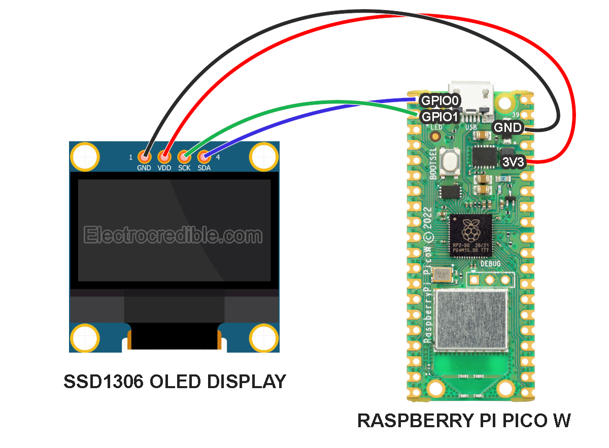
Connection Details:
| Raspberry Pi Pico Pins | OLED Display Pins |
| Pin 1 (GP0) | 4(SDA) |
| Pin 2 (GP1) | 3(SCL) |
| Pin 36(3.3 Volts Out) | 2(VDD) |
| Pin 38(GND) | 1(GND) |
Code to Scan I2C Devices
After proper connections have been made, we can now upload a script to scan all devices connected to the I2C bus. The following steps are explained using Thonny IDE. You can also use the uPyCraft IDE which is explained in this article.
- Copy the following code and paste it into a new project in Thonny IDE.
import machine
sdaPIN=machine.Pin(0)
sclPIN=machine.Pin(1)
i2c=machine.I2C(0,sda=sdaPIN, scl=sclPIN, freq=400000)
devices = i2c.scan()
if len(devices) != 0:
    print('Number of I2C devices found=',len(devices))
    for device in devices:
        print("Device Hexadecimel Address= ",hex(device))
else:
print("No device found")Code language: Python (python)- Run the script by clicking the green icon.

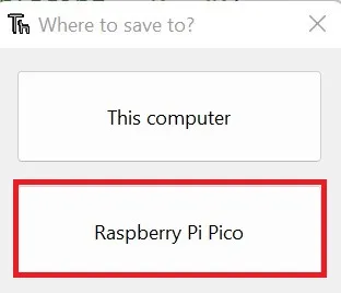
- Save the script as i2c_scan.py into your Pico.
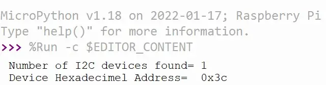
The shell window will output the device address, which confirms that the device has been detected by the I2C interface. Below is an image of the output shown in Thonny IDE, with 0x3C being returned as the I2C address of the OLED display.
The working of the I2C code is explained below after a few paragraphs.
Installation Of OLED Library
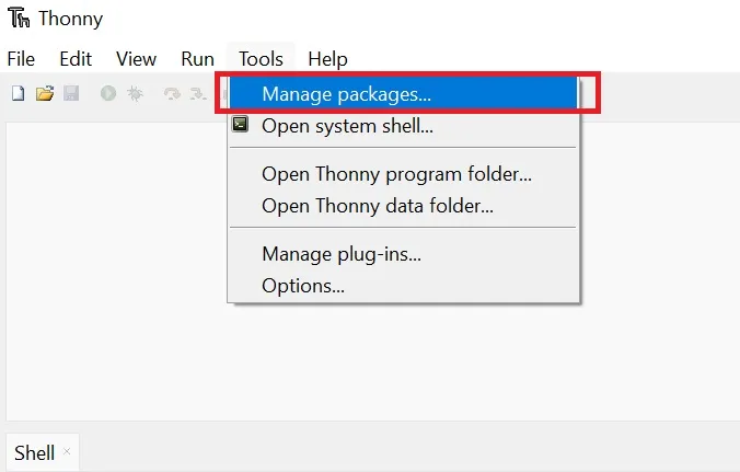
- Open Thonny IDE. On the top toolbar, click on Tools>Manage Packages.
- Type “micropython-ssd1306” on the search bar and press Enter. From the search results that appear, click on the library that you searched for.
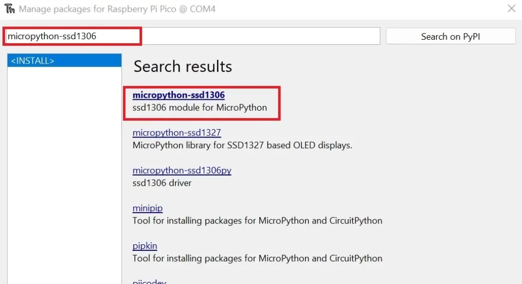
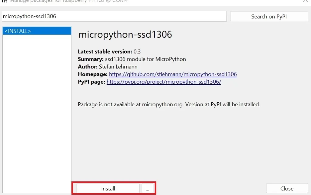
- In the next window, you can view some details of the library. The author of this library is Stefan Lehmann. Click on Install.
MicroPython Code for OLED Display
Ensure that all the connections are proper and the Pi Pico is connected to your computer. Open Thonny IDE and paste the following code into the main editor space.
# Source: Electrocredible.com, Language: MicroPython
from machine import Pin, I2C
from ssd1306 import SSD1306_I2C
WIDTH =128
HEIGHT= 64
i2c=I2C(0,scl=Pin(1),sda=Pin(0),freq=200000)
oled = SSD1306_I2C(WIDTH,HEIGHT,i2c)
while True:
oled.fill(0)
oled.text("Electrocredible", 0, 0)
oled.text("OLED interfacing", 0, 20)
oled.text("Tutorial", 0, 40)
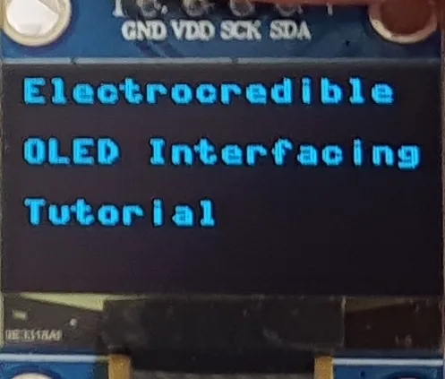
oled.show()Code language: Python (python)To run your script, Click the Run icon in the top toolbar or press F5 as we have shown in the image above. Give your script a file name with a ‘.py’ file name extension, for example, main.py. Your OLED display must now display texts as shown below.
How the I2C MicroPython Code Works
We first import the Pin module to control the GPIOs of Pi Pico, the I2C module to access ready-made functions for I2c, and SSD1306_I2C module to communicate easily with the OLED display. Then in lines 3 and 4, we specify the width and height of our display as 128 pixels and 64 pixels respectively.
from machine import Pin, I2C
from ssd1306 import SSD1306_I2C
WIDTH =128
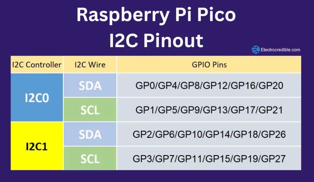
HEIGHT= 64Code language: Python (python)In the next line, we create an i2c instance of the machine.I2C class in MicroPython. In this constructor, we initialize four parameters inside the brackets- Peripheral ID(0), SCL pin(1), SDA pin(0), and the maximum frequency of the Serial Clock(200KHz). You might have to change the peripheral ID if you are connecting to some other pins. Take a look at the I2C pinout diagram above if you decide to use other pins. For pins connected to the I2C1 controller, change the peripheral ID to 1. The SDA and SCL pins also need to be specified as per the connection.
i2c=I2C(0,scl=Pin(1),sda=Pin(0),freq=200000)The function oled.text() takes three parameters- the String of text to be displayed, the value of the starting column pixel, and the value of the row pixel. For example, oled.text(“OLED interfacing”, 0, 20) will print the letters starting at the zeroth horizontal pixel(column) and 20th vertical pixel(row).
oled.text("Electrocredible", 0, 0)
oled.text("OLED interfacing", 0, 20)
oled.text("Tutorial", 0, 40)Code language: Python (python)
Finally, oled.show() will display the above three lines of text.

Software I2C in Raspberry Pi Pico
Software I2C can be used with any GPIO that can act as an output in Raspberry Pi Pico W. We have to import the class machine.SoftI2C to our MicroPython script for using software I2C. We can then declare an I2C instance as follows.
i2c = SoftI2C(scl=Pin(5), sda=Pin(4), freq=100_000)The rest of the I2C methods(such as reading and writing) are the same as those of hardware I2C.
How to Connect Multiple I2C Devices with Raspberry Pi Pico W
The two hardware I2C peripherals in Raspberry Pi Pico W can be accessed by 6 sets of GPIO pins per peripheral. This allows us to connect up to 12 devices in parallel. Software I2C allows the use of I2C with even more GPIO pins.
Moreover, two or more I2C devices can communicate with Pico W using the same bus. The devices need to have different addresses so that the master device (Pico W) can identify and communicate with other I2C devices connected to a single data bus.
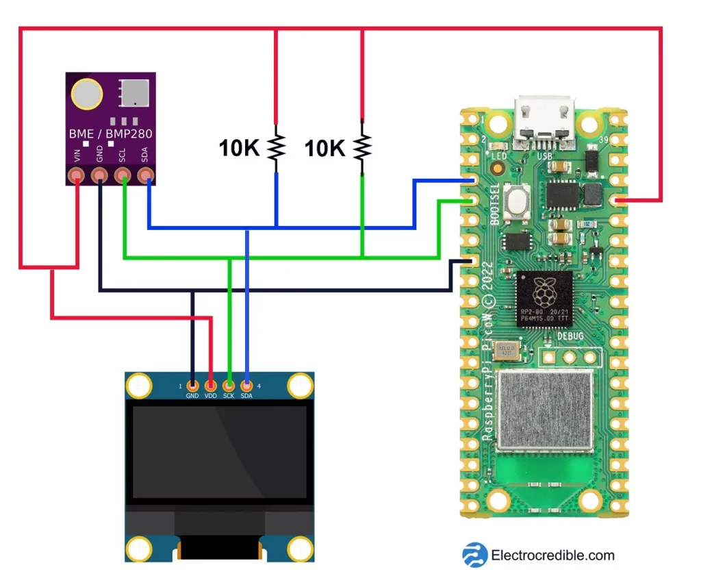
The schematic above shows a Raspberry Pi Pico W connected with a BME280 environmental sensor and an OLED display using the same bus. The I2C bus has GPIO 2 as the SDA pin and GPIO 3 as the SCL pin. The 10K pull-up resistors are included for reliable communication but can be omitted as both modules have inbuilt pull-up resistors.
This schematic is part of our guide: Use BME280 With Raspberry Pi Pico W & MicroPython Code.
Another helpful example to interface multiple I2C devices is: Raspberry Pi Pico With BMP280 – MicroPython Guide.
Useful MicroPython Functions For I2C Communication In Pico
i2c = I2C(0): Default statement to declare an i2c object with SCL Pin as 9 and SDA Pin as 8.i2c.scan(): Scan for peripherals, and returns a list of 7-bit addresses.i2c.writeto(42, b'123'): Write 3 bytes to the device with 42 as its address.i2c.readfrom(0x3a, 4): Read 4 bytes from the peripheral with its 7-bit address as 0x3a.I2C.start(): Generate a START condition on the bus.I2C.stop(): Generate a STOP condition on the bus.
For more details on using I2C in Micropython, read the MicroPython documentation here to learn about the machine.I2C class.
Final Thoughts & I2C Example Projects For Pico W
Apart from I2C, you can use BLE, Serial, and SPI communication in your Raspberry Pi Pico projects.
Here are some other examples where we use I2C for communicating with Raspberry Pi Pico:
- Raspberry Pi Pico LCD Tutorial-16×2 I2C Display(PCF8574) Interfacing Using MicroPython: In this project, we interface an LCD using TWI/I2C. If you don’t own an OLED display, this project is a good way to learn to use I2C using MicroPython.
- Raspberry Pi Pico BME280 Interfacing Guide Using MicroPython: BME280 is a temperature, pressure, and humidity sensor that communicates via I2C.
- Raspberry Pi Pico BMP280 Tutorial-Interface Using MicroPython: BMP280 is a temperature and pressure sensor that can communicate using I2C and SPI(Serial Peripheral Interface).
We hope you found this Raspberry Pi Pico I2C tutorial to be helpful. Thank you for reading.
Leave a Reply