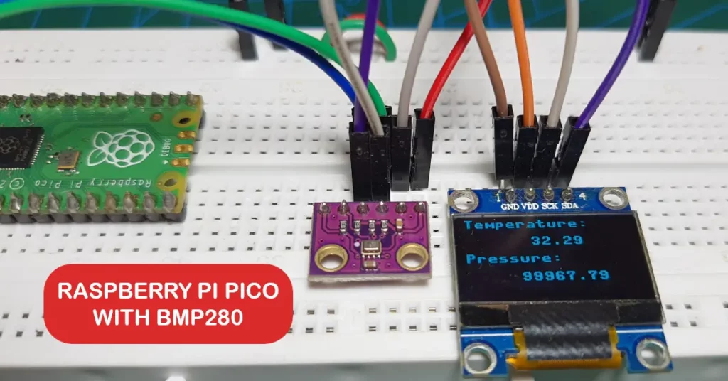
In this article, we will learn how to interface the BMP280 temperature and pressure sensor with Raspberry Pi Pico using MicroPython code. The connection diagram and detailed instructions are discussed step-by-step in this guide.
Overview of BMP280 Temperature & Pressure Sensor
The BMP280 is a barometric pressure and temperature sensor that can operate in extremely low currents such as 2.7 µA at 1Hz. Hence, it is an ideal sensor for mobile applications where power saving is crucial. It is 63% smaller than its predecessor, the BMP180. It can be interfaced using SPI and I2C protocols.
The image below shows the component layout and pinout of a GY-BMP280 sensor module.

BMP280 contains a Piezo-resistive pressure sensing element. This MEMS(Micro-electromechanical systems) sensor sends data to an ASIC (Application Specific Integrated Circuit) within the module. The ASIC sends data about temperature and pressure to external devices such as microcontrollers.
ⓘ Read our in-depth article on BMP280 where you can learn more about the sensor.
Components and Setup
- A Raspberry Pi Pico or Pico W.
- GY-BMP280 sensor module.
- A Breadboard and connecting wires(jumper/DuPont wires)
- USB cable(Micro-B).
- SSD1306 OLED display(Optional).
Your Raspberry Pi Pico needs to be flashed with a MicroPython UF2 file to program it in MicroPython. You can read our getting started guide for Raspberry Pi Pico where we show all the steps required to start programming Raspberry Pi Pico & Pico W. If you are using macOS, follow our guide to program Raspberry Pi Pico on macOS using Thonny IDE.
Also read: Arduino vs MicroPython vs CircuitPython: Which One Will You Choose?
How to Interface BMP280 with Raspberry Pi Pico
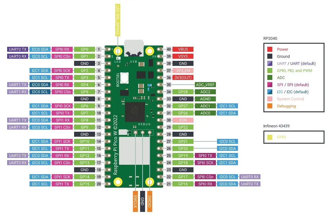
In this guide, we will use I2C to transmit data from BMP280 to Raspberry Pi Pico’s RP2040 microcontroller. The I2C interface needs 4 wires – 2 wires to send and synchronize data, and 2 wires for the power supply. Below is the pinout of Raspberry Pi Pico W for your reference. We can use any of the pins marked as SDA/SCL to interface with BMP280.
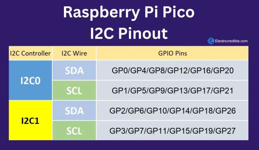
We will use GPIO-0 and GPIO-1 of Pi Pico to interface with BMP280. GPIO-0 is the SDA pin while GPIO-1 is the SCL pin. You can use any of the other I2C pins for your project. Read our article on I2C communication in Raspberry Pi Pico to learn more.
BMP280 & Raspberry Pi Pico Wiring
Connect the two devices as shown in the diagram below.

Connection Details:
| Raspberry Pi Pico Pin | BMP280 Pin |
| Pin 36(3V3OUT) | VCC |
| Pin 1(GP0) | SDA |
| Pin 2(GP1) | SCL |
| Pin 3(GND) | GND |
BMP280 MicroPython Library
To read the digital data from the BMP280 sensor, we will use a library (Link to library). The BMP280 MicroPython library has functions to read and write data to the BMP280.
After you have completed the connections as shown in the diagram, connect Raspberry Pi Pico to the computer.
Upload the following library code to Raspberry Pi Pico:
from micropython import const
from ustruct import unpack as unp

# Author David Stenwall Wahlund (david at dafnet.se)

# Power Modes
BMP280_POWER_SLEEP = const(0)
BMP280_POWER_FORCED = const(1)
BMP280_POWER_NORMAL = const(3)

BMP280_SPI3W_ON = const(1)
BMP280_SPI3W_OFF = const(0)

BMP280_TEMP_OS_SKIP = const(0)
BMP280_TEMP_OS_1 = const(1)
BMP280_TEMP_OS_2 = const(2)
BMP280_TEMP_OS_4 = const(3)
BMP280_TEMP_OS_8 = const(4)
BMP280_TEMP_OS_16 = const(5)

BMP280_PRES_OS_SKIP = const(0)
BMP280_PRES_OS_1 = const(1)
BMP280_PRES_OS_2 = const(2)
BMP280_PRES_OS_4 = const(3)
BMP280_PRES_OS_8 = const(4)
BMP280_PRES_OS_16 = const(5)

# Standby settings in ms
BMP280_STANDBY_0_5 = const(0)
BMP280_STANDBY_62_5 = const(1)
BMP280_STANDBY_125 = const(2)
BMP280_STANDBY_250 = const(3)
BMP280_STANDBY_500 = const(4)
BMP280_STANDBY_1000 = const(5)
BMP280_STANDBY_2000 = const(6)
BMP280_STANDBY_4000 = const(7)

# IIR Filter setting
BMP280_IIR_FILTER_OFF = const(0)
BMP280_IIR_FILTER_2 = const(1)
BMP280_IIR_FILTER_4 = const(2)
BMP280_IIR_FILTER_8 = const(3)
BMP280_IIR_FILTER_16 = const(4)

# Oversampling setting
BMP280_OS_ULTRALOW = const(0)
BMP280_OS_LOW = const(1)
BMP280_OS_STANDARD = const(2)
BMP280_OS_HIGH = const(3)
BMP280_OS_ULTRAHIGH = const(4)

# Oversampling matrix
# (PRESS_OS, TEMP_OS, sample time in ms)
_BMP280_OS_MATRIX = [
    [BMP280_PRES_OS_1, BMP280_TEMP_OS_1, 7],
    [BMP280_PRES_OS_2, BMP280_TEMP_OS_1, 9],
    [BMP280_PRES_OS_4, BMP280_TEMP_OS_1, 14],
    [BMP280_PRES_OS_8, BMP280_TEMP_OS_1, 23],
    [BMP280_PRES_OS_16, BMP280_TEMP_OS_2, 44]
]

# Use cases
BMP280_CASE_HANDHELD_LOW = const(0)
BMP280_CASE_HANDHELD_DYN = const(1)
BMP280_CASE_WEATHER = const(2)
BMP280_CASE_FLOOR = const(3)
BMP280_CASE_DROP = const(4)
BMP280_CASE_INDOOR = const(5)

_BMP280_CASE_MATRIX = [
    [BMP280_POWER_NORMAL, BMP280_OS_ULTRAHIGH, BMP280_IIR_FILTER_4, BMP280_STANDBY_62_5],
    [BMP280_POWER_NORMAL, BMP280_OS_STANDARD, BMP280_IIR_FILTER_16, BMP280_STANDBY_0_5],
    [BMP280_POWER_FORCED, BMP280_OS_ULTRALOW, BMP280_IIR_FILTER_OFF, BMP280_STANDBY_0_5],
    [BMP280_POWER_NORMAL, BMP280_OS_STANDARD, BMP280_IIR_FILTER_4, BMP280_STANDBY_125],
    [BMP280_POWER_NORMAL, BMP280_OS_LOW, BMP280_IIR_FILTER_OFF, BMP280_STANDBY_0_5],
    [BMP280_POWER_NORMAL, BMP280_OS_ULTRAHIGH, BMP280_IIR_FILTER_16, BMP280_STANDBY_0_5]
]

_BMP280_REGISTER_ID = const(0xD0)
_BMP280_REGISTER_RESET = const(0xE0)
_BMP280_REGISTER_STATUS = const(0xF3)
_BMP280_REGISTER_CONTROL = const(0xF4)
_BMP280_REGISTER_CONFIG = const(0xF5)  # IIR filter config

_BMP280_REGISTER_DATA = const(0xF7)


class BMP280:
    def __init__(self, i2c_bus, addr=0x76, use_case=BMP280_CASE_HANDHELD_DYN):
        self._bmp_i2c = i2c_bus
        self._i2c_addr = addr

        # read calibration data
        # < little-endian
        # H unsigned short
        # h signed short
        self._T1 = unp('<H', self._read(0x88, 2))[0]
        self._T2 = unp('<h', self._read(0x8A, 2))[0]
        self._T3 = unp('<h', self._read(0x8C, 2))[0]
        self._P1 = unp('<H', self._read(0x8E, 2))[0]
        self._P2 = unp('<h', self._read(0x90, 2))[0]
        self._P3 = unp('<h', self._read(0x92, 2))[0]
        self._P4 = unp('<h', self._read(0x94, 2))[0]
        self._P5 = unp('<h', self._read(0x96, 2))[0]
        self._P6 = unp('<h', self._read(0x98, 2))[0]
        self._P7 = unp('<h', self._read(0x9A, 2))[0]
        self._P8 = unp('<h', self._read(0x9C, 2))[0]
        self._P9 = unp('<h', self._read(0x9E, 2))[0]

        # output raw
        self._t_raw = 0
        self._t_fine = 0
        self._t = 0

        self._p_raw = 0
        self._p = 0

        self.read_wait_ms = 0  # interval between forced measure and readout
        self._new_read_ms = 200  # interval between
        self._last_read_ts = 0

        if use_case is not None:
            self.use_case(use_case)

    def _read(self, addr, size=1):
        return self._bmp_i2c.readfrom_mem(self._i2c_addr, addr, size)

    def _write(self, addr, b_arr):
        if not type(b_arr) is bytearray:
            b_arr = bytearray([b_arr])
        return self._bmp_i2c.writeto_mem(self._i2c_addr, addr, b_arr)

    def _gauge(self):
        # TODO limit new reads
        # read all data at once (as by spec)
        d = self._read(_BMP280_REGISTER_DATA, 6)

        self._p_raw = (d[0] << 12) + (d[1] << 4) + (d[2] >> 4)
        self._t_raw = (d[3] << 12) + (d[4] << 4) + (d[5] >> 4)

        self._t_fine = 0
        self._t = 0
        self._p = 0

    def reset(self):
        self._write(_BMP280_REGISTER_RESET, 0xB6)

    def load_test_calibration(self):
        self._T1 = 27504
        self._T2 = 26435
        self._T3 = -1000
        self._P1 = 36477
        self._P2 = -10685
        self._P3 = 3024
        self._P4 = 2855
        self._P5 = 140
        self._P6 = -7
        self._P7 = 15500
        self._P8 = -14600
        self._P9 = 6000

    def load_test_data(self):
        self._t_raw = 519888
        self._p_raw = 415148

    def print_calibration(self):
        print("T1: {} {}".format(self._T1, type(self._T1)))
        print("T2: {} {}".format(self._T2, type(self._T2)))
        print("T3: {} {}".format(self._T3, type(self._T3)))
        print("P1: {} {}".format(self._P1, type(self._P1)))
        print("P2: {} {}".format(self._P2, type(self._P2)))
        print("P3: {} {}".format(self._P3, type(self._P3)))
        print("P4: {} {}".format(self._P4, type(self._P4)))
        print("P5: {} {}".format(self._P5, type(self._P5)))
        print("P6: {} {}".format(self._P6, type(self._P6)))
        print("P7: {} {}".format(self._P7, type(self._P7)))
        print("P8: {} {}".format(self._P8, type(self._P8)))
        print("P9: {} {}".format(self._P9, type(self._P9)))

    def _calc_t_fine(self):
        # From datasheet page 22
        self._gauge()
        if self._t_fine == 0:
            var1 = (((self._t_raw >> 3) - (self._T1 << 1)) * self._T2) >> 11
            var2 = (((((self._t_raw >> 4) - self._T1)
                      * ((self._t_raw >> 4)
                         - self._T1)) >> 12)
                    * self._T3) >> 14
            self._t_fine = var1 + var2

    @property
    def temperature(self):
        self._calc_t_fine()
        if self._t == 0:
            self._t = ((self._t_fine * 5 + 128) >> 8) / 100.
        return self._t

    @property
    def pressure(self):
        # From datasheet page 22
        self._calc_t_fine()
        if self._p == 0:
            var1 = self._t_fine - 128000
            var2 = var1 * var1 * self._P6
            var2 = var2 + ((var1 * self._P5) << 17)
            var2 = var2 + (self._P4 << 35)
            var1 = ((var1 * var1 * self._P3) >> 8) + ((var1 * self._P2) << 12)
            var1 = (((1 << 47) + var1) * self._P1) >> 33

            if var1 == 0:
                return 0

            p = 1048576 - self._p_raw
            p = int((((p << 31) - var2) * 3125) / var1)
            var1 = (self._P9 * (p >> 13) * (p >> 13)) >> 25
            var2 = (self._P8 * p) >> 19

            p = ((p + var1 + var2) >> 8) + (self._P7 << 4)
            self._p = p / 256.0
        return self._p

    def _write_bits(self, address, value, length, shift=0):
        d = self._read(address)[0]
        m = int('1' * length, 2) << shift
        d &= ~m
        d |= m & value << shift
        self._write(address, d)

    def _read_bits(self, address, length, shift=0):
        d = self._read(address)[0]
        return d >> shift & int('1' * length, 2)

    @property
    def standby(self):
        return self._read_bits(_BMP280_REGISTER_CONFIG, 3, 5)

    @standby.setter
    def standby(self, v):
        assert 0 <= v <= 7
        self._write_bits(_BMP280_REGISTER_CONFIG, v, 3, 5)

    @property
    def iir(self):
        return self._read_bits(_BMP280_REGISTER_CONFIG, 3, 2)

    @iir.setter
    def iir(self, v):
        assert 0 <= v <= 4
        self._write_bits(_BMP280_REGISTER_CONFIG, v, 3, 2)

    @property
    def spi3w(self):
        return self._read_bits(_BMP280_REGISTER_CONFIG, 1)

    @spi3w.setter
    def spi3w(self, v):
        assert v in (0, 1)
        self._write_bits(_BMP280_REGISTER_CONFIG, v, 1)

    @property
    def temp_os(self):
        return self._read_bits(_BMP280_REGISTER_CONTROL, 3, 5)

    @temp_os.setter
    def temp_os(self, v):
        assert 0 <= v <= 5
        self._write_bits(_BMP280_REGISTER_CONTROL, v, 3, 5)

    @property
    def press_os(self):
        return self._read_bits(_BMP280_REGISTER_CONTROL, 3, 2)

    @press_os.setter
    def press_os(self, v):
        assert 0 <= v <= 5
        self._write_bits(_BMP280_REGISTER_CONTROL, v, 3, 2)

    @property
    def power_mode(self):
        return self._read_bits(_BMP280_REGISTER_CONTROL, 2)

    @power_mode.setter
    def power_mode(self, v):
        assert 0 <= v <= 3
        self._write_bits(_BMP280_REGISTER_CONTROL, v, 2)

    @property
    def is_measuring(self):
        return bool(self._read_bits(_BMP280_REGISTER_STATUS, 1, 3))

    @property
    def is_updating(self):
        return bool(self._read_bits(_BMP280_REGISTER_STATUS, 1))

    @property
    def chip_id(self):
        return self._read(_BMP280_REGISTER_ID, 2)

    @property
    def in_normal_mode(self):
        return self.power_mode == BMP280_POWER_NORMAL

    def force_measure(self):
        self.power_mode = BMP280_POWER_FORCED

    def normal_measure(self):
        self.power_mode = BMP280_POWER_NORMAL

    def sleep(self):
        self.power_mode = BMP280_POWER_SLEEP

    def use_case(self, uc):
        assert 0 <= uc <= 5
        pm, oss, iir, sb = _BMP280_CASE_MATRIX[uc]
        p_os, t_os, self.read_wait_ms = _BMP280_OS_MATRIX[oss]
        self._write(_BMP280_REGISTER_CONFIG, (iir << 2) + (sb << 5))
        self._write(_BMP280_REGISTER_CONTROL, pm + (p_os << 2) + (t_os << 5))

    def oversample(self, oss):
        assert 0 <= oss <= 4
        p_os, t_os, self.read_wait_ms = _BMP280_OS_MATRIX[oss]
        self._write_bits(_BMP280_REGISTER_CONTROL, p_os + (t_os << 3), 2)Code language: Python (python)
Save the file to Rpi Pico with the filename bmp280.py.
MicroPython Code to Read BMP280
With the library in place, let us write a script to read data from BMP280. Copy the following code, and save it in your Raspberry Pi Pico with a “.py” extension file name. You can name it main.py. Code saved as main.py in the flash memory of Pico runs automatically on reboot.
# Source: Electrocredible.com, Language: MicroPython

from machine import Pin,I2C
from bmp280 import *
import time

sdaPIN=machine.Pin(0)
sclPIN=machine.Pin(1)
bus = I2C(0,sda=sdaPIN, scl=sclPIN, freq=400000)
time.sleep(0.1)
bmp = BMP280(bus)

bmp.use_case(BMP280_CASE_INDOOR)

while True:
    pressure=bmp.pressure
    p_bar=pressure/100000
    p_mmHg=pressure/133.3224
    temperature=bmp.temperature
    print("Temperature: {} C".format(temperature))
    print("Pressure: {} Pa, {} bar, {} mmHg".format(pressure,p_bar,p_mmHg))
    time.sleep(1)Code language: Python (python)
Upon running the code, here is how the output looks in the shell of Thonny IDE:

Did you know? There is an in-built temperature sensor in Raspberry Pi Pico W. To use it, read our article – Raspberry Pi Pico Onboard Temperature Sensor Tutorial Using MicroPython.

BMP280 MicroPython Code Explained
We first import the necessary libraries in the first 3 lines of our code.
from machine import Pin,I2C
from bmp280 import *
import timeCode language: JavaScript (javascript)
The SDA and SCL pins are set in the next lines of code. Also, an object called bmp of the BMP280 class is created with the I2C parameters.
sdaPIN=machine.Pin(0)
sclPIN=machine.Pin(1)
bus = I2C(0,sda=sdaPIN, scl=sclPIN, freq=400000)
time.sleep(0.1)
bmp = BMP280(bus)Code language: Python (python)
BMP280 comes with various Use Cases for the sensor to be used in different environments. Below is the table describing how Use Cases relate to other parameters.
| Use Case | Mode | Oversampling Setting | Pressure Oversampling | Temperature Oversampling | IIR Filter Coefficient |
|---|---|---|---|---|---|
| Handheld device Low-power (e.g. mobile device) | Normal | Ultra-high resolution | (×)16 | (×)2 | (×)4 |
| Handheld device dynamic | Normal | Standard resolution | (×)4 | (×)1 | (×)16 |
| Weather monitoring (lowest power consumption) | Forced | Ultra-low power | (×)1 | (×)1 | (×)Off |
| Elevator/floor change detection | Normal | Standard resolution | (×)4 | (×)1 | (×)4 |
| Drop detection | Normal | Low power | (×)2 | (×)1 | (×)Off |
| Indoor navigation(All parameters in maximum) | Normal | Ultra-high resolution | (×)16 | (×)2 | (×)16 |
The BMP280 can be operated in three power modes: Sleep mode, Forced mode, and Normal mode. To learn more about the modes, oversampling, and IIR filter, you can refer to the datasheet of BMP280 that we linked earlier. Choose any one of the use cases depending on your application. Here we are using the settings for Indoor Navigation use case as it gives very ultra-high resolution readings.
bmp.use_case(BMP280_CASE_INDOOR)Code language: CSS (css)The variable pressure holds the value of pressure returned by the bmp.pressure function. The unit of this value is in Pascal(Pa). We also convert it to bar and mmHg which are the two other units of measuring pressure. The pressure value in Pascal is divided by 100000 and 133.3224 to get the values in bar and mmHg respectively.
pressure=bmp.pressure
p_bar=pressure/100000
p_mmHg=pressure/133.3224Code language: Python (python)
The following line of code stores the temperature value (Celcius) in the variable called temperature.
temperature=bmp.temperatureWe finally print the values of pressure and temperature and introduce a delay of 1 second.
print("Temperature: {} C".format(temperature))
print("Pressure: {} Pa, {} bar, {} mmHg".format(pressure,p_bar,p_mmHg))
time.sleep(1)Code language: Python (python)
Show BMP280 Data on OLED Display
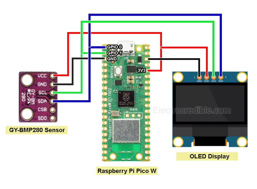
Let us now connect a 128×64 OLED display to our project to view the sensor readings easily. Connect Raspberry Pi Pico, OLED display, and BMP280 as shown in the schematic below.
Upload the following library for the SSD1306 OLED display and save it as ssd1306.py.
from micropython import const
import framebuf

# register definitions
SET_CONTRAST = const(0x81)
SET_ENTIRE_ON = const(0xA4)
SET_NORM_INV = const(0xA6)
SET_DISP = const(0xAE)
SET_MEM_ADDR = const(0x20)
SET_COL_ADDR = const(0x21)
SET_PAGE_ADDR = const(0x22)
SET_DISP_START_LINE = const(0x40)
SET_SEG_REMAP = const(0xA0)
SET_MUX_RATIO = const(0xA8)
SET_COM_OUT_DIR = const(0xC0)
SET_DISP_OFFSET = const(0xD3)
SET_COM_PIN_CFG = const(0xDA)
SET_DISP_CLK_DIV = const(0xD5)
SET_PRECHARGE = const(0xD9)
SET_VCOM_DESEL = const(0xDB)
SET_CHARGE_PUMP = const(0x8D)

# Subclassing FrameBuffer provides support for graphics primitives
# http://docs.micropython.org/en/latest/pyboard/library/framebuf.html
class SSD1306(framebuf.FrameBuffer):
    def __init__(self, width, height, external_vcc):
        self.width = width
        self.height = height
        self.external_vcc = external_vcc
        self.pages = self.height // 8
        self.buffer = bytearray(self.pages * self.width)
        super().__init__(self.buffer, self.width, self.height, framebuf.MONO_VLSB)
        self.init_display()

    def init_display(self):
        for cmd in (
            SET_DISP | 0x00,  # off
            # address setting
            SET_MEM_ADDR,
            0x00,  # horizontal
            # resolution and layout
            SET_DISP_START_LINE | 0x00,
            SET_SEG_REMAP | 0x01,  # column addr 127 mapped to SEG0
            SET_MUX_RATIO,
            self.height - 1,
            SET_COM_OUT_DIR | 0x08,  # scan from COM[N] to COM0
            SET_DISP_OFFSET,
            0x00,
            SET_COM_PIN_CFG,
            0x02 if self.width > 2 * self.height else 0x12,
            # timing and driving scheme
            SET_DISP_CLK_DIV,
            0x80,
            SET_PRECHARGE,
            0x22 if self.external_vcc else 0xF1,
            SET_VCOM_DESEL,
            0x30,  # 0.83*Vcc
            # display
            SET_CONTRAST,
            0xFF,  # maximum
            SET_ENTIRE_ON,  # output follows RAM contents
            SET_NORM_INV,  # not inverted
            # charge pump
            SET_CHARGE_PUMP,
            0x10 if self.external_vcc else 0x14,
            SET_DISP | 0x01,
        ):  # on
            self.write_cmd(cmd)
        self.fill(0)
        self.show()

    def poweroff(self):
        self.write_cmd(SET_DISP | 0x00)

    def poweron(self):
        self.write_cmd(SET_DISP | 0x01)

    def contrast(self, contrast):
        self.write_cmd(SET_CONTRAST)
        self.write_cmd(contrast)

    def invert(self, invert):
        self.write_cmd(SET_NORM_INV | (invert & 1))

    def show(self):
        x0 = 0
        x1 = self.width - 1
        if self.width == 64:
            # displays with width of 64 pixels are shifted by 32
            x0 += 32
            x1 += 32
        self.write_cmd(SET_COL_ADDR)
        self.write_cmd(x0)
        self.write_cmd(x1)
        self.write_cmd(SET_PAGE_ADDR)
        self.write_cmd(0)
        self.write_cmd(self.pages - 1)
        self.write_data(self.buffer)


class SSD1306_I2C(SSD1306):
    def __init__(self, width, height, i2c, addr=0x3C, external_vcc=False):
        self.i2c = i2c
        self.addr = addr
        self.temp = bytearray(2)
        self.write_list = [b"\x40", None]  # Co=0, D/C#=1
        super().__init__(width, height, external_vcc)

    def write_cmd(self, cmd):
        self.temp[0] = 0x80  # Co=1, D/C#=0
        self.temp[1] = cmd
        self.i2c.writeto(self.addr, self.temp)

    def write_data(self, buf):
        self.write_list[1] = buf
        self.i2c.writevto(self.addr, self.write_list)


class SSD1306_SPI(SSD1306):
    def __init__(self, width, height, spi, dc, res, cs, external_vcc=False):
        self.rate = 10 * 1024 * 1024
        dc.init(dc.OUT, value=0)
        res.init(res.OUT, value=0)
        cs.init(cs.OUT, value=1)
        self.spi = spi
        self.dc = dc
        self.res = res
        self.cs = cs
        import time

        self.res(1)
        time.sleep_ms(1)
        self.res(0)
        time.sleep_ms(10)
        self.res(1)
        super().__init__(width, height, external_vcc)

    def write_cmd(self, cmd):
        self.spi.init(baudrate=self.rate, polarity=0, phase=0)
        self.cs(1)
        self.dc(0)
        self.cs(0)
        self.spi.write(bytearray([cmd]))
        self.cs(1)

    def write_data(self, buf):
        self.spi.init(baudrate=self.rate, polarity=0, phase=0)
        self.cs(1)
        self.dc(1)
        self.cs(0)
        self.spi.write(buf)
        self.cs(1)
Finally, upload the following script to your Pi Pico to show the data from BMP280 on the OLED display.
# Source: Electrocredible.com, Language: MicroPython
from machine import Pin,I2C
from bmp280 import *
from ssd1306 import SSD1306_I2C
import time
bus = I2C(0,sda=Pin(0), scl=Pin(1), freq=400000)
time.sleep(0.1)
bmp = BMP280(bus)
bmp.use_case(BMP280_CASE_INDOOR)
WIDTH =128
HEIGHT= 64
i2c=I2C(0,scl=Pin(1),sda=Pin(0),freq=200000)
oled = SSD1306_I2C(WIDTH,HEIGHT,i2c)
while True:
pressure=bmp.pressure
p_bar=pressure/100000
p_mmHg=pressure/133.322
temperature=bmp.temperature
oled.text("Temperature:", 0, 0)
oled.text(str(temperature), 50, 15)
oled.text("Pressure:", 0, 30)
oled.text(str(pressure), 40, 45)
oled.show()
time.sleep(1)
oled.fill(0)
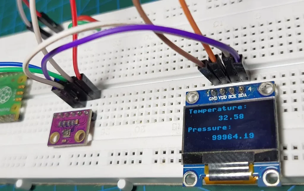
Code language: Python (python)Save it as main.py or any other name with a “.py” file extension. When you run the code, the OLED display must show readings similar to the image below.
Code Explanation:
We set the width, and height of the OLED display and also created an oled object with I2C parameters.
WIDTH =128
HEIGHT= 64
i2c=I2C(0,scl=Pin(1),sda=Pin(0),freq=200000)
oled = SSD1306_I2C(WIDTH,HEIGHT,i2c)Code language: Python (python)
The oled.text() function takes 3 parameters: string, x-position & y-position. We print the temperature and pressure on different lines using this function. The str(temperature) function converts the temperature value to a string.
oled.text("Temperature:", 0, 0)
oled.text(str(temperature), 50, 15)
oled.text("Pressure:", 0, 30)
oled.text(str(pressure), 40, 45)Code language: Python (python)
The function oled.show() prints the contents on the display. After an interval of 1 second, oled.fill(0) function clears the display so that the next reading can be shown.
oled.show()
time.sleep(1)
oled.fill(0)Code language: Python (python)
To learn more about how an OLED display is interfaced with Pi Pico, follow the tutorial Raspberry Pi Pico OLED Display Interfacing Tutorial Using MicroPython.
Wrapping Up
I hope you found this tutorial on Raspberry Pi Pico BMP280 interfacing to be helpful. Like the BMP280, BME280 is a sensor that can give readings of temperature, pressure, and humidity. This 3-in-one sensor is almost the same in all aspects as the BMP280, with the added benefit of an accurate humidity sensor. You can read about how to interface it with Raspberry Pi Pico in our article Raspberry Pi Pico BME280 Interfacing Guide Using MicroPython.
DHT22 and DHT11 are two other sensors that can give us temperature and humidity. We also have detailed guides on these sensors:
- Raspberry Pi Pico DHT22(AM2302) Interfacing Tutorial – Temperature And Humidity On OLED Display Using MicroPython
- Raspberry Pi Pico DHT11 MicroPython – Easy Interfacing Guide
Please leave your thoughts or queries in the comments below. Thank you for reading.
Leave a Reply