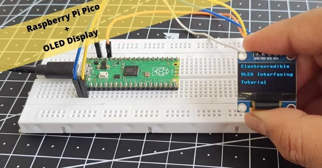
In this tutorial, we will learn to interface Raspberry Pi Pico with an SSD1306 OLED display easily. MicroPython code is used to interface the two devices.
Many kinds of displays are used in microcontroller projects, such as e-ink displays, LCDs, 7-segment displays, and OLED displays. OLED displays are convenient as they have a fast refresh rate, better visibility, low power consumption, and high pixel density. Moreover, they can be easily interfaced using the I2C and SPI communication interfaces.
Overview of SSD1306 OLED Display
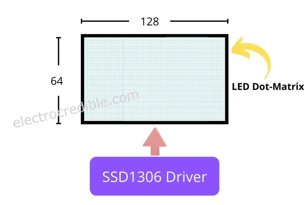
SSD1306 is a controller chip that can control 128×64 dot matrix diode displays. 128 and 64 refer to the horizontal and vertical pixels respectively i.e. there are 128 pixels horizontally on the display and 64 pixels vertically, arranged in a rectangular matrix.
Features of SSD1306:
- Power Supply: 3V – 5V.
- On-chip low-power RC oscillator.
- Communication interface: Parallel interface, 3/4 wire SPI, I2C interface.
- Programmable Frame Rate.
- Operating temperature range: -40°C to 85°C.
Prerequisites & Setup
- A Raspberry Pi Pico or Pico W.
- 4 Pin I2C OLED display module (size: 0.96inch/2.44cm; 128×64).
- Breadboard and connecting wires.
Your Raspberry Pi Pico needs to be flashed with a MicroPython UF2 file to program it in MicroPython. You can read our getting started guide for Raspberry Pi Pico where we show all the steps required to start programming Raspberry Pi Pico & Pico W. If you are using macOS, follow our guide to program Raspberry Pi Pico on macOS using Thonny IDE.
I2C is a communication protocol commonly used in embedded systems. It can facilitate communication between multiple devices using just a two-wire bus. Read more about I2C and how we can use the I2C in Pi Pico in our article Raspberry Pi Pico I2C Communication Guide.
I2C Pins in Raspberry Pi Pico to Interface OLED
The Raspberry Pi Pico has two I2C ports. You can access these ports with various GPIO pins. Take a look at the pin diagram below.
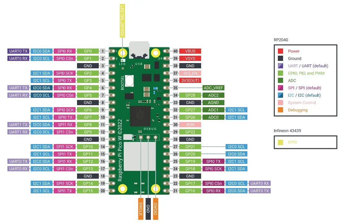
As seen in the pinout diagram, many pins function as SDA and SCL. These pins are connected to either of the two I2C ports internally. We can choose any of these pins to interface with the OLED display.
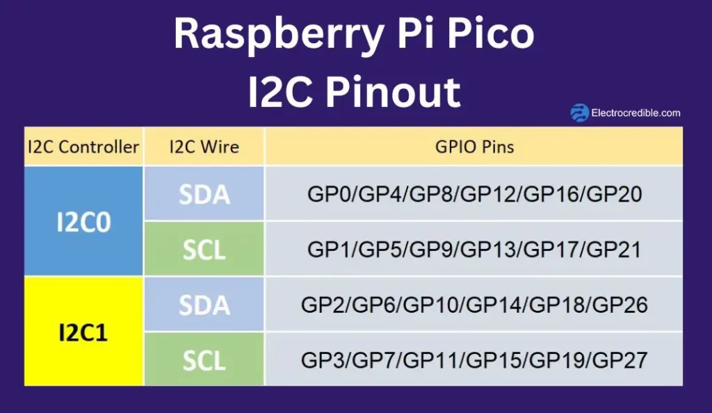
I2C requires 4 wires for communication- Positive voltage, Ground, SDA, and SCL. SDA stands for Serial Data. This wire sends the bits to communicate between two or more entities. SCL stands for Serial Clock. This wire is responsible for the synchronization of data.
Here we shall use the pin GPIO 0 as SDA and GPIO 1 as SCL.

Wiring Raspberry Pi Pico W with SSD1306 OLED Display
Connect your Raspberry Pi Pico/Pico W to the SSD1306 OLED display module as shown below.
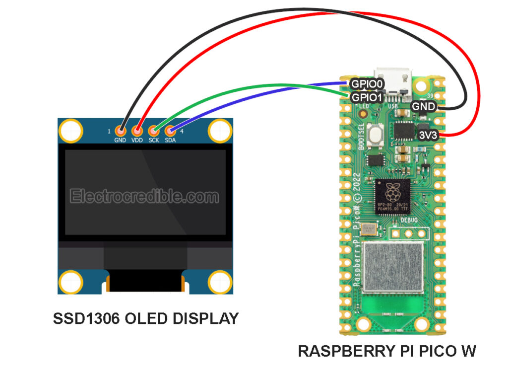
Pin-to-Pin connection details:
| Raspberry Pi Pico Pin | OLED Display Pin |
| Pin 1 (GPIO0) | 4(SDA) |
| Pin 2 (GPIO1) | 3(SCL) |
| Pin 36(3.3 Volts Out) | 2(VDD) |
| Pin 38(GND) | 1(GND) |
Installation of MicroPython OLED Library
To communicate with the OLED display, we need to send certain commands with precise delays between the commands. Thankfully, there is a library that takes care of all the commands.
Upload the following code to Raspberry Pi Pico and save it as ssd1306.py.
# MicroPython SSD1306 OLED driver, I2C and SPI interfaces

from micropython import const
import framebuf


# register definitions
SET_CONTRAST = const(0x81)
SET_ENTIRE_ON = const(0xA4)
SET_NORM_INV = const(0xA6)
SET_DISP = const(0xAE)
SET_MEM_ADDR = const(0x20)
SET_COL_ADDR = const(0x21)
SET_PAGE_ADDR = const(0x22)
SET_DISP_START_LINE = const(0x40)
SET_SEG_REMAP = const(0xA0)
SET_MUX_RATIO = const(0xA8)
SET_COM_OUT_DIR = const(0xC0)
SET_DISP_OFFSET = const(0xD3)
SET_COM_PIN_CFG = const(0xDA)
SET_DISP_CLK_DIV = const(0xD5)
SET_PRECHARGE = const(0xD9)
SET_VCOM_DESEL = const(0xDB)
SET_CHARGE_PUMP = const(0x8D)

# Subclassing FrameBuffer provides support for graphics primitives
# http://docs.micropython.org/en/latest/pyboard/library/framebuf.html
class SSD1306(framebuf.FrameBuffer):
    def __init__(self, width, height, external_vcc):
        self.width = width
        self.height = height
        self.external_vcc = external_vcc
        self.pages = self.height // 8
        self.buffer = bytearray(self.pages * self.width)
        super().__init__(self.buffer, self.width, self.height, framebuf.MONO_VLSB)
        self.init_display()

    def init_display(self):
        for cmd in (
            SET_DISP | 0x00,  # off
            # address setting
            SET_MEM_ADDR,
            0x00,  # horizontal
            # resolution and layout
            SET_DISP_START_LINE | 0x00,
            SET_SEG_REMAP | 0x01,  # column addr 127 mapped to SEG0
            SET_MUX_RATIO,
            self.height - 1,
            SET_COM_OUT_DIR | 0x08,  # scan from COM[N] to COM0
            SET_DISP_OFFSET,
            0x00,
            SET_COM_PIN_CFG,
            0x02 if self.width > 2 * self.height else 0x12,
            # timing and driving scheme
            SET_DISP_CLK_DIV,
            0x80,
            SET_PRECHARGE,
            0x22 if self.external_vcc else 0xF1,
            SET_VCOM_DESEL,
            0x30,  # 0.83*Vcc
            # display
            SET_CONTRAST,
            0xFF,  # maximum
            SET_ENTIRE_ON,  # output follows RAM contents
            SET_NORM_INV,  # not inverted
            # charge pump
            SET_CHARGE_PUMP,
            0x10 if self.external_vcc else 0x14,
            SET_DISP | 0x01,
        ):  # on
            self.write_cmd(cmd)
        self.fill(0)
        self.show()

    def poweroff(self):
        self.write_cmd(SET_DISP | 0x00)

    def poweron(self):
        self.write_cmd(SET_DISP | 0x01)

    def contrast(self, contrast):
        self.write_cmd(SET_CONTRAST)
        self.write_cmd(contrast)

    def invert(self, invert):
        self.write_cmd(SET_NORM_INV | (invert & 1))

    def show(self):
        x0 = 0
        x1 = self.width - 1
        if self.width == 64:
            # displays with width of 64 pixels are shifted by 32
            x0 += 32
            x1 += 32
        self.write_cmd(SET_COL_ADDR)
        self.write_cmd(x0)
        self.write_cmd(x1)
        self.write_cmd(SET_PAGE_ADDR)
        self.write_cmd(0)
        self.write_cmd(self.pages - 1)
        self.write_data(self.buffer)


class SSD1306_I2C(SSD1306):
    def __init__(self, width, height, i2c, addr=0x3C, external_vcc=False):
        self.i2c = i2c
        self.addr = addr
        self.temp = bytearray(2)
        self.write_list = [b"\x40", None]  # Co=0, D/C#=1
        super().__init__(width, height, external_vcc)

    def write_cmd(self, cmd):
        self.temp[0] = 0x80  # Co=1, D/C#=0
        self.temp[1] = cmd
        self.i2c.writeto(self.addr, self.temp)

    def write_data(self, buf):
        self.write_list[1] = buf
        self.i2c.writevto(self.addr, self.write_list)


class SSD1306_SPI(SSD1306):
    def __init__(self, width, height, spi, dc, res, cs, external_vcc=False):
        self.rate = 10 * 1024 * 1024
        dc.init(dc.OUT, value=0)
        res.init(res.OUT, value=0)
        cs.init(cs.OUT, value=1)
        self.spi = spi
        self.dc = dc
        self.res = res
        self.cs = cs
        import time

        self.res(1)
        time.sleep_ms(1)
        self.res(0)
        time.sleep_ms(10)
        self.res(1)
        super().__init__(width, height, external_vcc)

    def write_cmd(self, cmd):
        self.spi.init(baudrate=self.rate, polarity=0, phase=0)
        self.cs(1)
        self.dc(0)
        self.cs(0)
        self.spi.write(bytearray([cmd]))
        self.cs(1)

    def write_data(self, buf):
        self.spi.init(baudrate=self.rate, polarity=0, phase=0)
        self.cs(1)
        self.dc(1)
        self.cs(0)
        self.spi.write(buf)
        self.cs(1)
If you are using the Thonny IDE, here are the steps to upload a library or any script to Raspberry Pi Pico:
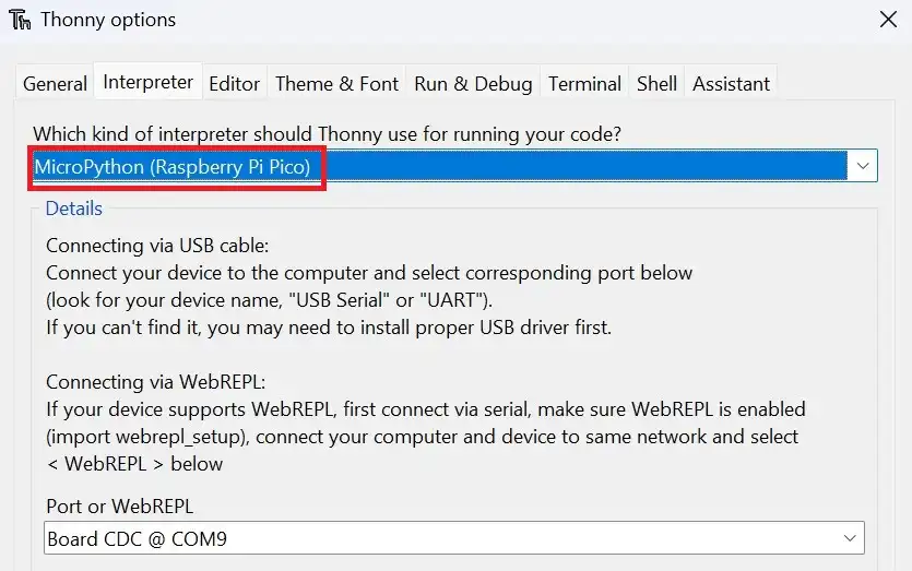
1. With all connections done according to the schematic, connect the Pico to your computer using a USB cable. Open Thonny IDE and set the interpreter to use MicroPython on Raspberry Pi Pico.
2. Go to File>New in Thonny IDE to create a new project.
3. Paste your code into the new project.
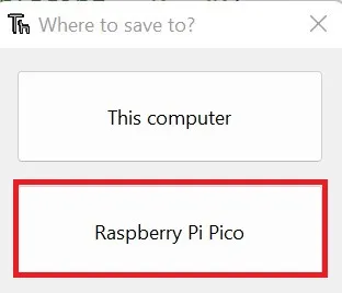
4. Click on File>Save as and select the save location as Raspberry Pi Pico.
5. Save the code with a proper filename. Save as ssd1306.py for this example.
MicroPython Code to Interface Raspberry Pi Pico with OLED
Let us now write a simple script to interface the OLED display with Raspberry Pi Pico. This script will make function calls to the ssd1306.py library we installed earlier.
Copy and paste the following code and save it as main.py on Raspberry Pi Pico.
# Source: Electrocredible.com, Language: MicroPython
# Import necessary modules
from machine import Pin, I2C
from ssd1306 import SSD1306_I2C
import time
# Pin numbers for I2C communication
sda_pin=0
scl_pin=1
# Display dimensions
WIDTH =128
HEIGHT= 64
# Set up I2C communication
i2c=I2C(0,scl=scl_pin,sda=sda_pin,freq=200000)
time.sleep(0.1)
# Initialize SSD1306 display with I2C interface
oled = SSD1306_I2C(WIDTH,HEIGHT,i2c)
while True:
# Clear the display
oled.fill(0)
# text, x-position, y-position
oled.text("Hello,", 42, 20)
oled.text("World !", 38, 40)
# Show the updated display
oled.show()
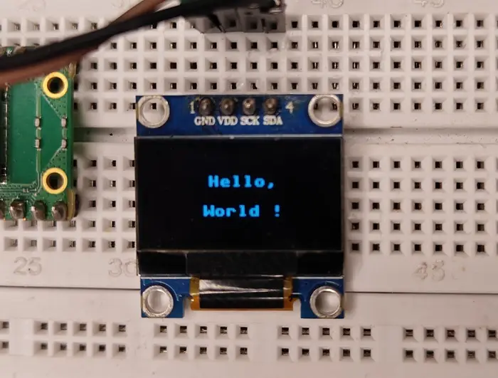
Code language: Python (python)Run the code(Press the F5 keyboard shortcut in Thonny IDE to run code). Your OLED display should now display the words as shown in the image below.
If you want to display dynamic text or values, such as data from sensors, be sure to type oled.fill(0) at the beginning or end of the main loop. This will clear the display every time the main loop runs. If you don’t clear the display, the characters will overlap each other and the text will be incomprehensible.
Scrolling Text Animation
The framebuf module of MicroPython comes with a built-in method to display scrolling text. We can scroll text by using oled.scroll(xstep, ystep) method. It takes two arguments. The arguments specify the number of pixels by which the text will be shifted on the x-axis and y-axis respectively.
Here, the code scrolls the text 1 position to the left by setting ‘xstep’ to -1. We repeat this in a loop 128 times by setting the loop range to ‘WIDTH’.
Upload the following script to scroll a line of text:
# Source: Electrocredible.com, Language: MicroPython
from machine import Pin, I2C
from ssd1306 import SSD1306_I2C
import time
WIDTH =128
HEIGHT= 64
i2c=I2C(0,scl=Pin(1),sda=Pin(0),freq=200000)
time.sleep(0.1)
oled = SSD1306_I2C(WIDTH,HEIGHT,i2c)
while True:
    oled.text("Scrolling text",10, 32)
    for i in range (WIDTH):
        oled.show()
        oled.scroll(-1,0)
        time.sleep(0.01)Code language: Python (python)
Demonstration
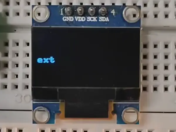
Due to the frame rate of the camera, the screen refresh rate is visible in the video but is invisible to the human eye.
Display Graphics on OLED Display
The framebuf module has some useful prebuilt functions to display simple Bitmap graphics on an OLED display.
Horizontal Line
The oled.hline(x, y, w, c) method takes four parameters. The x-position of the starting end of the line is the argument ‘x’, the y-position is ‘y’, ‘w’ is the width of the line, and ‘c’ should be set to ‘1’ for monochrome display. Enter the following code in your main program to see the results.
oled.text("Horizontal Line", 0, 0)
oled.hline(0,32,128,1)
oled.show()Code language: Python (python)
Vertical Line
The oled.vline(x, y, w, c) method works in the same way as the one above. Here ‘w’ indicates the vertical length of the line in pixels.
oled.text("Vertical Line", 0, 0)
oled.vline(64,20,40,1)
oled.show()Code language: Python (python)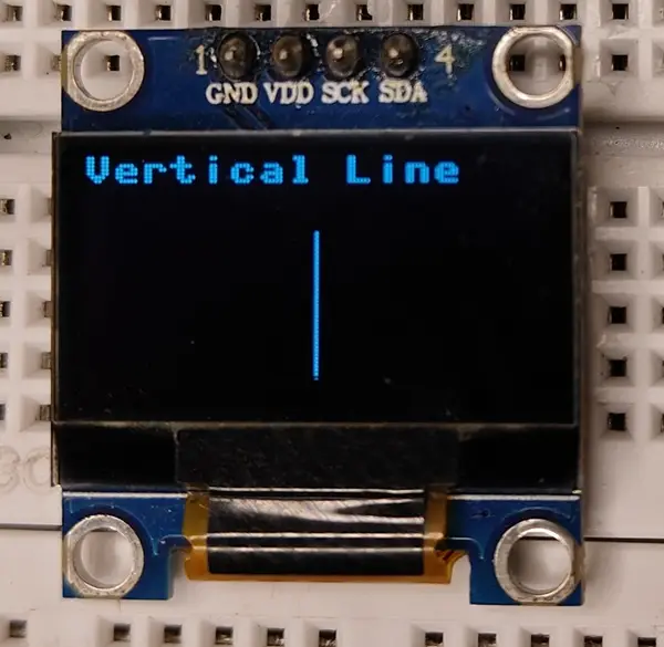
Rectangle
Use the function oled.rect(x, y, w, h, c) to display a rectangle. x,y is the position of the pixel on the top-left corner, and w and h denote the width and height of the rectangle respectively.
oled.text("Rectangle", 0, 0)
oled.rect(32,16,64,32,1)
oled.show()Code language: Python (python)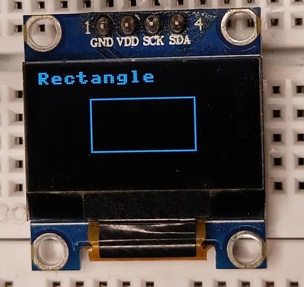
You can also display a filled rectangle by using the oled.fill_rect(x, y, w, h, c) method.
oled.text("Filled Rectangle", 0, 0)
oled.fill_rect(32, 16, 64, 32, 1)
oled.show()Code language: Python (python)
Troubleshooting: “OSError: [Errno 5] EIO” & “[Errno 110] ETIMEDOUT”
This errors are commonly encountered while interfacing SSD1306 display using MicroPython. Here are some possible solutions:
- This issue is often caused by wrong or loose wire connections. I faced this issue because of a defective jumper wire.
- This problem may also occur if your OLED module does not have pull-up resistors for the SDA and SCL lines. Manually pull the SDA and SCK pins to the 3.3 Volts using 4.7K or 10K pull-up resistors.
- Sometimes, just disconnecting and reconnecting the USB cable solves the issue.
- Adding a small delay after initializing the
i2cinstance also helps in avoiding this issue.
Wrapping Up
If you want to experiment further, here is a project that uses an OLED display: Raspberry Pi Pico DHT22(AM2302) Interfacing Tutorial. Please comment below if you have any queries regarding this Raspberry Pi Pico OLED display tutorial. Thanks for reading and have a fun time making projects!
Also Read: Interface Raspberry Pi Pico W With TM1637 4-Digit 7-Segment Display
Leave a Reply