In this tutorial, you will learn to interface a relay with Raspberry Pi Pico. An example is shown to control the relay via a web server. The Raspberry Pi Pico’s web server will be coded in MicroPython along with the necessary code required to control the relay.
The web server will be accessible in the local network and can be accessed by any device connected to the same network. The web server will dynamically display the status of the relay and will provide an easy Graphical User Interface GUI to interact with the relay.
Components and Setup
- A Raspberry Pi Pico development board.
- A 2-channel 5V relay module.
- Breadboard and connecting wires.
- AC bulb, wires and plug to be controlled by a relay.
Your Raspberry Pi Pico needs to be flashed with MicroPython firmware. You can read our getting started guide for Raspberry Pi Pico where we show all steps required to start programming RP2040 in MicroPython.
How a Relay Works
A relay works by using an electromagnet to activate a switch. The core of the electromagnet, commonly constructed of iron, is wrapped in a coil of wire. A metal armature or movable contact that is attached to a switch is drawn to the magnetic field produced when an electrical current passes through the coil.

The armature connects the NC(Normally Connected) terminal to the COMMON terminal in idle condition. When the current is turned on, the COMMON terminal is connected to the NO(Normally Open) terminal, thereby completing the circuit. The switch is opened and the circuit is broken when the current is cut off because the magnetic field vanishes and the armature is no longer drawn to it.
Relay Module Pinout and Overview
The image below shows the pinout of a 2-channel relay module.

Pin description:
| PIN | DESCRIPTION |
| COM | The common pin either makes contact with the NO or NC terminal, depending on the state of the relay. |
| NO | Normally open terminal. When the relay is not powered this terminal stays open, i.e. not connected to the COM pin. |
| NC | Normally closed terminal. When the relay is not powered, this terminal stays closed, i.e. it is shorted with the COM pin. |
| VCC and GND | These pins are used to supply power to the board. The VCC voltage needs to be 5V for this module. |
| IN1 and IN2: | The control pins for the 2 relays. Connecting these pins to GND will move the relays from the NO to the NC position. |
| JD-VCC: | This pin is also named RY-VCC in some relay modules. This pin is used to provide an external power supply to the relay. Suppose you want to control a 12V-operated relay with a 5V-compatible microcontroller. Then we can use this pin to connect an external 12V source to operate the relay. |
There are different relay modules with different numbers of channels such as 1-channel relay, 2-channel relay, or 8-channel relay. The more the number of channels, the more devices we can control. Below are some relay modules shown with different numbers of channels. All of these can be interfaced using similar logic as described in this article.

Schematic of Raspberry Pi Pico W with Relay Module
⚠ Warning: Please be careful while dealing with mains voltage as it can shock you. Seek help from an experienced individual if required. Proceed with caution!
The circuit diagram below shows the connection of a 2-channel relay module with Raspberry Pi Pico W.
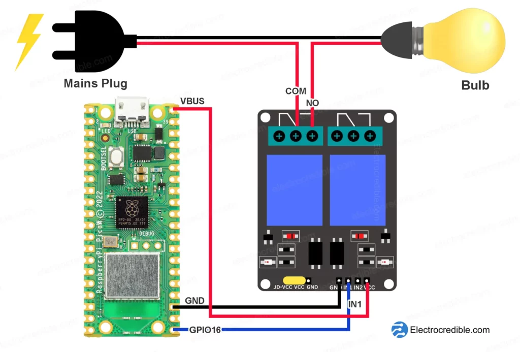
The VBUS pin of Raspberry Pi Pico is used to supply 5V supply to the relay module. The JD-VCC is shorted to the VCC pin using a jumper cap, represented in yellow in the diagram. GPIO16 is wired to the IN1 pin. The mains wire is connected in such a way that the lightbulb remains off when the relay is not powered. The NO terminal will be shorted internally with the COM terminal when we connect the IN1 pin to the ground using code.
Note that although the Raspberry Pi Pico GPIOs can output only up to 3.3V, it will be able to control a 5V compatible relay. However, the power supply to the relay module needs to be at least 5V, so we have taken the supply from the VBUS pin.
Note that you use other PINs of Raspberry Pi Pico to interface the relay. Check out our Raspberry Pi Pico Pinout guide to learn more.

MicroPython Code to Control Relay with Raspberry Pi Pico
Let us see a simple example to control a relay using Raspberry Pi Pico. The code will toggle a relay at regular intervals.
Upload the following code using your preferred IDE:
from machine import Pin
import time

# setup relay pin as output
relay = Pin(16, Pin.OUT)

while True:
    # turn on relay
    relay.value(0)
    #print relay state
    print("Relay On")
    time.sleep(1)
    # turn off relay
    relay.value(1)
    #print relay state
    print("Relay Off")
    time.sleep(1)Code language: PHP (php)
How to Upload the Code
Here are the steps to upload code if you use Thonny IDE.
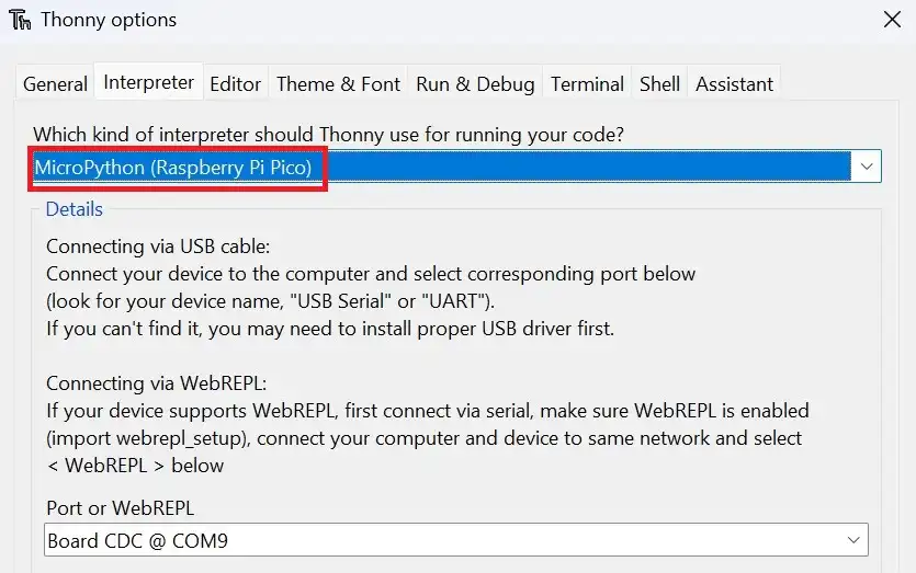
1. After the wiring of the relay to Pico is done, connect your Pico to your computer. Set the interpreter of Thonny to use MicroPython on Raspberry Pi Pico.
2. Paste the code into a new project(File>New).
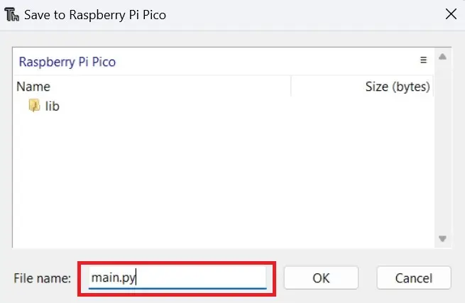
3. Click on File>Save as and select the save location as Raspberry Pi Pico.
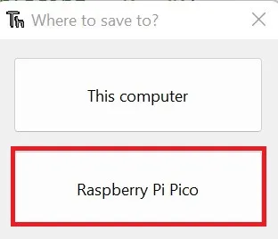
4. Name the code file as main.py.
5. Run the code by clicking the Run button or by pressing F5.

The relay must now toggle on and off with an interval of 1 second in between.
Code Explanation
GPIO16 is set as the output pin for the relay. In the while loop, the code alternately sets the relay pin’s value to 0 (turning the relay on) and 1 (turning the relay off) and sleeps for one second in between. The print statements are included to give feedback about the relay’s state on the shell of the IDE.
Web Server to Control Relay
Let us now program a simple web server that will present us with a Graphical User Interface(GUI) to control the relay using any web browser. Please copy and paste the following code into your IDE and run it.
#Source: Electrocredible.com
from machine import Pin
import network
import socket
import time

relay = Pin(16, Pin.OUT)
relay.value(1)
relayState= "Relay is OFF"

led=Pin("LED", Pin.OUT)

ssid = 'MyNetwork'
password = 'MyPassword'

wlan = network.WLAN(network.STA_IF)
wlan.active(True)
wlan.connect(ssid, password)

html = """<!DOCTYPE html>
<html>
   <head>
      <title>Pico Relay Control Web Server</title>
      <meta charset="UTF-8">
      <meta name="viewport" content="width=device-width, initial-scale=1">

      <style>html{font-family: Arial; display:inline-block; margin: 0px auto; text-align: center;}
         h1{font-family: Arial; color: #2551cc;}
         .button1{-webkit-border-radius: 28; -moz-border-radius: 28; border-radius: 28px; font-family: Arial; color: #ffffff;
         font-size: 30px; background: #2ba615; padding: 10px 20px 10px 20px; text-decoration: none;}
         .button2{-webkit-border-radius: 28; -moz-border-radius: 28; border-radius: 28px; font-family: Arial; color: #ffffff;
         font-size: 30px; background: #f52e45; padding: 10px 20px 10px 20px; text-decoration: none;}
      </style>
   </head>
   <body>
      <h1>Pico Relay Control Web Server</h1>
      <p>%s</p>
      <p><a href="/relay/on"><button class="button1">ON</button></a></p>
      <p><a href="/relay/off"><button class="button2">OFF</button></a></p>
   </body>
</html>
"""

# Wait for connect or fail
max_wait = 10
while max_wait > 0:
    if wlan.status() < 0 or wlan.status() >= 3:
        break
    max_wait -= 1
    print('waiting for connection...')
    time.sleep(1)

# Handle connection error
if wlan.status() != 3:
    raise RuntimeError('network connection failed')
else:
    print('connected')
    status = wlan.ifconfig()
    print( 'ip = ' + status[0] )
    for i in range (6):
        led.toggle()
        time.sleep_ms(200)

addr = socket.getaddrinfo('0.0.0.0', 80)[0][-1]
s = socket.socket()
s.bind(addr)
s.listen(1)
print('listening on', addr)

while True:
    try:
        cl, addr = s.accept()
        print('client connected from', addr)
        request = cl.recv(1024)
        print(request)

        request = str(request)
        relay_on = request.find('/relay/on')
        relay_off = request.find('/relay/off')
        print( 'relay on = ' + str(relay_on))
        print( 'relay off = ' + str(relay_off))

        if relay_on == 6:
            print("relay on")
            relay.value(0)
            relayState = "Relay is ON"

        if relay_off == 6:
            print("relay off")
            relay.value(1)
            relayState = "Relay is OFF"

        response = html % relayState
        cl.send('HTTP/1.0 200 OK\r\nContent-type: text/html\r\n\r\n')
        cl.send(response)
        cl.close()

    except OSError as e:
        cl.close()
        print('connection closed')
Code language: Python (python)
Replace the MyNetwork and MyPassword according to the network that you are connecting to.
When you run the code, the shell will display an IP address. Also, the onboard LED in Pico will blink three times when the connection is established.

Enter the IP address in the browser of a device(computer/smartphone) connected to the same network.
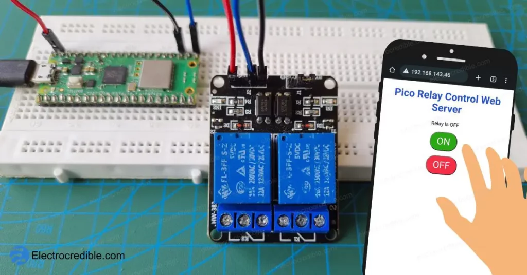
Your device must now display a GUI similar to the one shown below.

Tapping on the ‘ON’ button must switch on the relay and the ‘OFF’ button must switch it off. The status of the relay is also shown onscreen.
The web server demonstrated here is synchronous. To create an asynchronous web server, you can follow our guide – Raspberry Pi Pico W Asynchronous Web Server – MicroPython Code.
Code Explanation
After setting GPIO16 as the output pin for the relay, it is initialized in the OFF state. Note that the relay’s coil is energized only when the control pin is connected to the ground. So the function relay.value(1) does not energize the relay coil.
relay = Pin(16, Pin.OUT)
relay.value(1)
relayState= "Relay is OFF"Code language: Python (python)
Replace the network credentials with your Wi-Fi SSID and password.
ssid = 'MyNetwork'
password = 'MyPassword'Code language: JavaScript (javascript)
The wlan object is created in the station mode. You can read more about connecting to a network on Raspberry Pi Pico in our in-depth article.
wlan = network.WLAN(network.STA_IF)
wlan.active(True)
wlan.connect(ssid, password)Code language: Python (python)
Next, we create a socket object ‘s’ and listen for connections from a client.
# Open socket
addr = socket.getaddrinfo('0.0.0.0', 80)[0][-1]
s = socket.socket()
s.bind(addr)
s.listen(1)Code language: Python (python)
In the while loop, we implement exception handling through the try block to communicate with a client. The IP address used to connect and the request received is printed in the shell.
    try:
        cl, addr = s.accept()
        print('client connected from', addr)
        request = cl.recv(1024)
        print(request)Code language: Python (python)
We look for /relay/on and /relay/off in the URL entered by the client. The request from the client is converted to a string and the value is printed on the shell. For example, if we enter the URL ‘192.168.x.x/relay/on‘ in the address bar of our device, we will get an output such as “relay on= 6” in the shell.
        request = str(request)
        relay_on = request.find('/relay/on')
        relay_off = request.find('/relay/off')
        print( 'relay on = ' + str(relay_on))
        print( 'relay off = ' + str(relay_off))Code language: Python (python)
If the request from the client has /relay/on, we print the output in the shell as “relay on”, and then turn the relay ON by using the function relay.value(0). The relayState variable is used to send dynamic data to the server, which will be displayed in the GUI.
        if relay_on == 6:
            print("relay on")
            relay.value(0)
            relayState = "Relay is ON"Code language: Python (python)
Next, we send the HTML page to be displayed to the client that we had created in the code. Also, relayState is sent as a response which will let the user know if the relay is on or off. The connection is closed using cl.close() at the end.
        response = html % relayState
        cl.send('HTTP/1.0 200 OK\r\nContent-type: text/html\r\n\r\n')
        cl.send(response)
        cl.close()Code language: Python (python)
Wrapping Up
Here is the video of the 2-channel relay module controlled by an Android device via a web server on Raspberry Pi Pico W.
We hope you found the detailed steps to interface a relay with Raspberry Pi Pico and control it via a web server to be helpful. Using this guide, you can control AC devices easily via pushbuttons or from anywhere via the web.
Check out another project that uses a relay with Raspberry Pi Pico W:
Please leave your thoughts and queries in the comments below.
Leave a Reply