What is Kirchhoff’s Current Law Or KCL?
Kirchhoff’s Current Law (KCL) is a fundamental principle in electrical circuit analysis, named after the German physicist Gustav Kirchhoff. In essence, KCL states that the total current flowing into a node in an electrical circuit is equal to the total current flowing out of that node, regardless of the complexity of the circuit. In an electric circuit, a ‘node’ is a point where two or more electrical components or wires meet. KCL and KVL(Kirchhoff’s Voltage Law) are two of the most useful laws used in circuit analysis.
Kirchhoff’s first law or KCL is based on the principle of conservation of charge, which dictates that the total charge in a closed circuit remains constant over time i.e. charge cannot be created or destroyed, only transferred from one object to another. The principle of conservation of charge is a fundamental principle of physics and has been confirmed by experiments.
Kirchhoff’s Current Law is applicable to both AC and DC circuits.
Mathematical Expression Of KCL
Mathematically, KCL can be expressed as:
$\sum_{}^{}I_{in}+\sum_{}^{}I_{out}=0$, where Σ IIN is the summation of currents entering a node and Σ IOUT is the summation of currents exiting the same node.
According to Kirchhoff’s current law, “In a lumped electric circuit, the algebraic sum of all currents entering and leaving a node must be equal to zero at any point of time”. Note the significance of the term “algebraic sum” which denotes that we add the currents while taking account of their signs. In a “lumped circuit”, the electrical components are assumed to be ideal and the connecting wires are assumed to be of zero resistance.
Sign Convention in KCL
The current in each branch must be given a direction in order to apply KCL, and the sign convention establishes the current’s direction with regard to a node. Conventionally, a positive sign is given to the current entering the node, and a negative sign is given to the current exiting the node. This practice ensures that the node’s total currents are equal to zero.

In the node, as shown in the image, the currents I1 and I2 are entering the node while I3 and I4 are leaving the node.
Thus, according to KCl, we can represent the currents by the equation:
I1 + I2 – I3 – I4=0 i.e. Σ(currents entering and leaving a node)=0
KCL Example: KCL At A Junction
Consider the circuit shown below consisting of 2 resistors. Resistors Ra and Rb are in parallel with each other. The resistor combination is connected to a DC voltage source with voltage ‘Vs‘ Volts.

Let us consider the current entering ‘Node A’ as I1, the current through Ra as I2, and the current through Rb as I3. Conventionally, current flows from the positive terminal to the negative terminal of the battery. The current I1 divides into I2 and I3 in ‘Node A’, and at ‘Node B’, we see that the currents add up to the initial value.
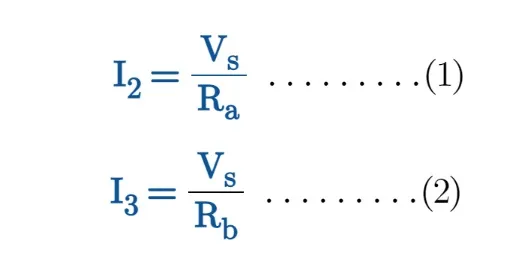
The voltage between the ends of the resistors Ra and Rb is equal to the supply voltage Vs. So by Ohm’s law, we obtain the current flowing through the resistors Ra and Rb as:
The total resistance ‘Rt‘ across the voltage source is the result of Ra and Rb in parallel, given by:

Using Ohm’s law, we can find I1 by dividing V by Rt.

If we add I2 and I3, we get:

From equations (4) and (5), it is evident that I1 = I2 + I3, which is in accordance with KCL.

Why We Need KCL?
KCL can be applied to a circuit to determine unknown currents and voltages. KCL may be applied to each node in the circuit to create a series of simultaneous equations that can be solved to determine the current and voltage values in the circuit. KCL and Ohms’s law are crucial for ‘Nodal Analysis’ of circuits.
Leave a Reply