This tutorial will guide you to interface the BME280 environment sensor with Arduino. The Bosch BME280 is a three-in-one environment sensor that can sense temperature, humidity, and pressure. This makes it ideal for use in projects such as mini weather stations. In this guide, we will use the Arduino UNO development board and program it using Arduino IDE version 2.
Overview Of BME280 Environment Sensor
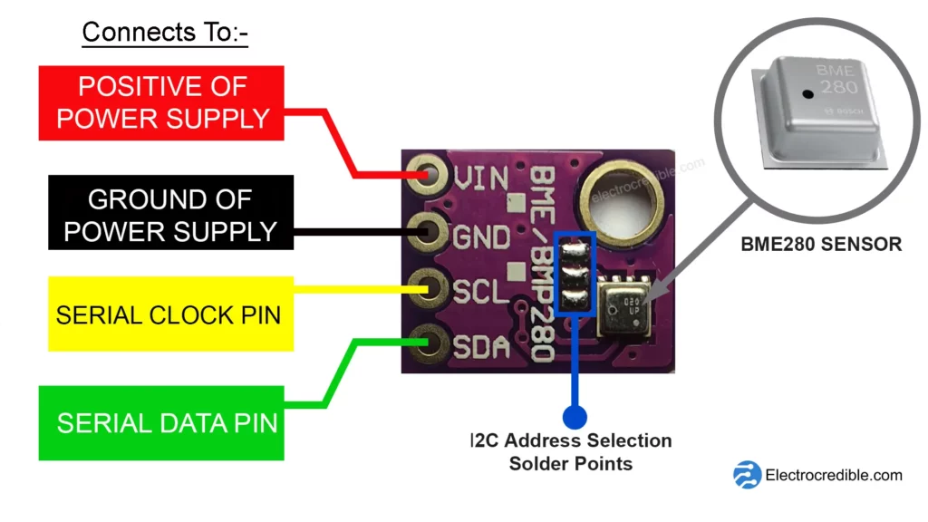
The Bosch BME280 generates digital data containing information on humidity, pressure, and temperature. Its performance is comparable to the BMP280 temperature and pressure sensor. The sensor can be used in a wide array of applications such as indoor climate control, indoor navigation, smart irrigation, elevator floor change detection, etc. The pinout and board description are shown in the images below.
BME280 Environment Sensor Pinout
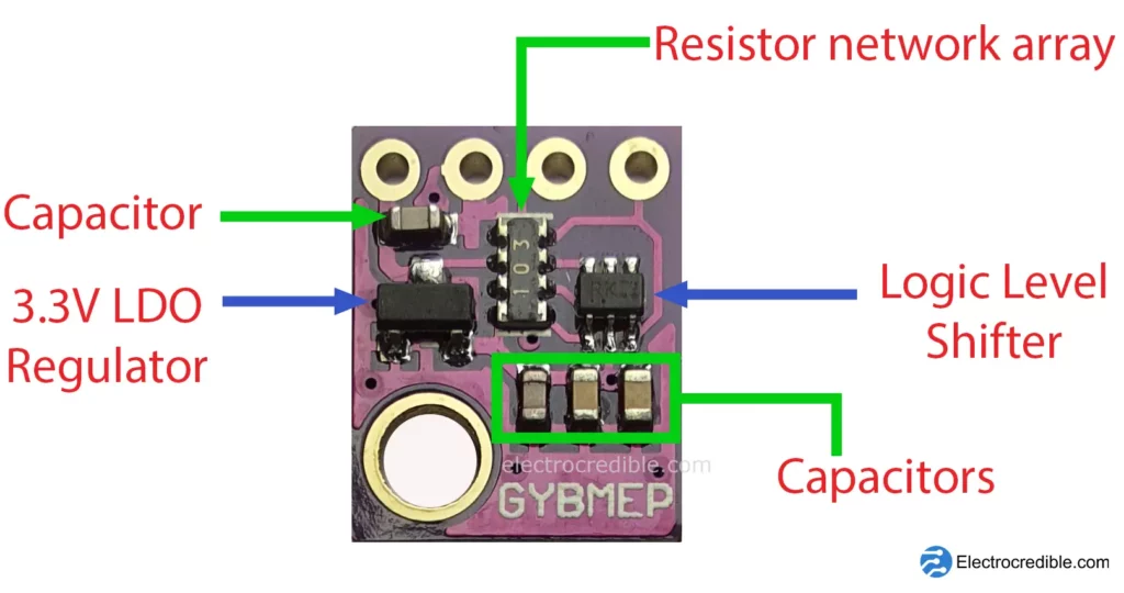
GY-BME280 Breakout Board Component Layout
The breakout board has some components together with the BME280 sensor to make it easier to interface. A 3.3V LDO regulator and a logic level shifter helps us to connect it with both 5V and 3.3V compatible microcontrollers.
GY-BME280 Specifications
Here are some specifications of the BME280 environment sensor module.
Temperature sensor specs:
- Accuracy: ±1.0 °C from 0 to 65 °C
- Range: 0 to 65 °C
- Resolution: 0.01 °C
Humidity sensor specs:
- Accuracy: ±3% (at 25°C)
- Range: 0 to 100%
- Resolution: 0.008 %RH
Pressure sensor specs:
- Accuracy: ±1.0 hPa (from 0 to 65 °C)
- Range: 300 to 1100 hPa
- Resolution: 0.18 Pa
The cheap and commonly used DHT11 humidity sensor has a range of 20% to 80%(within 0-50°C) with ±5% accuracy and 1% RH resolution. Thus BME280 can be used when higher accuracy, range, and resolution is desired.
For more information on BME280, read our article BME280 Pinout, Specs, Applications.
Installation Of BME280 Library In Arduino IDE
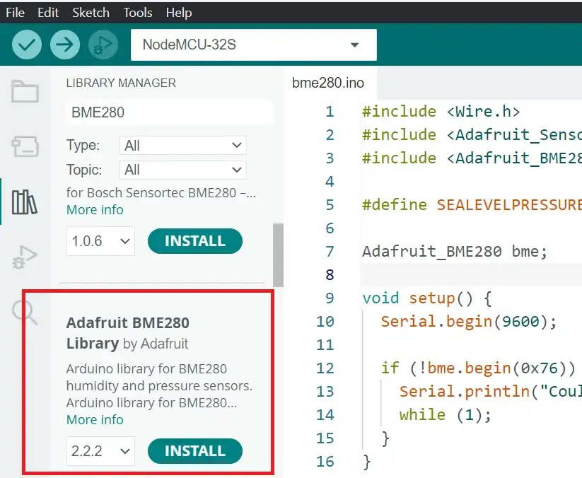
Go to Tools>Manage Libraries, or click the Library Manager icon on the left sidebar.
Search for BME280. Scroll down till you find Adafruit BME280 Library and click on install.
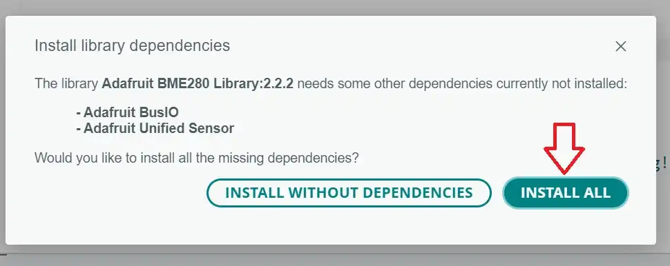
The Adafruit BME280 library also requires two additional libraries for it to work- the Adafruit BusIO & Adafruit Unified Sensor libraries. If you have not installed these libraries before, a prompt will appear for you to install these dependencies. Click on INSTALL ALL.
On successful installation, you can see the following on the terminal output screen.

Restart the Arduino IDE after the libraries are successfully installed.
Wiring BME280 With Arduino
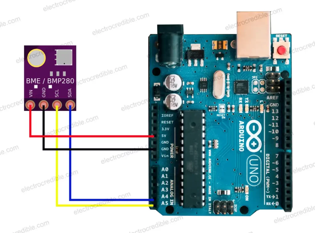
The connection diagram above shows how we can interface the GY-BME280 environment sensor with Arduino UNO. For other boards, make sure you are connecting the designated pins for I2C communication.
Wiring details:
| BME280 Pin | Arduino UNO Pin | Arduino Nano Pin | Arduino Mega Pin |
| SDA | A4 | A4 | 20 |
| SCL | A5 | A5 | 21 |

Arduino Environment Sensor Arduino Code
Connect your Arduino UNO to your computer using a USB cable. On Arduino IDE 2, Select the board you are using.
For example, you can select Arduino UNO by going to Tools> Boards> Arduino AVR Boards> Arduino UNO. Also, select the PORT to the one your board is connected to by going to Tools> Board.

We will use the I2C communication interface to communicate with the environment sensor. You can also use SPI communication.
Adafruit provides a ready-made library for interfacing GY-BME280 module with Arduino. You can find it in Arduino IDE by going to File > Examples. Scroll till you find Adafruit BME280 library and select the example named bme280test.
Or, you can copy the code given below and paste it into Arduino IDE. It is slightly modified to remove redundant code.
#include <Wire.h>
#include <SPI.h>
#include <Adafruit_Sensor.h>
#include <Adafruit_BME280.h>

#define SEALEVELPRESSURE_HPA (1013.25)

Adafruit_BME280 bme;
unsigned long delayTime;

void setup() {
    Serial.begin(9600);
    while(!Serial);
    Serial.println(F("BME280 test"));
    unsigned status;
    status = bme.begin(0x76);

    if (!status) {
        Serial.println("Could not find a valid BME280 sensor, check wiring, address, sensor ID!");
        Serial.print("SensorID was: 0x"); Serial.println(bme.sensorID(),16);
        Serial.print("        ID of 0xFF probably means a bad address, a BMP 180 or BMP 085\n");
        Serial.print("   ID of 0x56-0x58 represents a BMP 280,\n");
        Serial.print("        ID of 0x60 represents a BME 280.\n");
        Serial.print("        ID of 0x61 represents a BME 680.\n");
        while (1) delay(10);
    }

    Serial.println("-- Default Test --");
    delayTime = 1000;

    Serial.println();
}

void loop() {
    printValues();
    delay(delayTime);
}

void printValues() {
    Serial.print("Temperature = ");
    Serial.print(bme.readTemperature());
    Serial.println(" °C");

    Serial.print("Pressure = ");

    Serial.print(bme.readPressure() / 100.0F);
    Serial.println(" hPa");

    Serial.print("Approx. Altitude = ");
    Serial.print(bme.readAltitude(SEALEVELPRESSURE_HPA));
    Serial.println(" m");

    Serial.print("Humidity = ");
    Serial.print(bme.readHumidity());
    Serial.println(" %");

    Serial.println();
}Code language: C++ (cpp)
Upload the code to your Arduino board using Ctrl+U or by clicking on the upload icon.
To view the output of BME280, open the serial monitor by going to Tools> Serial Monitor. You should see an output as shown below.
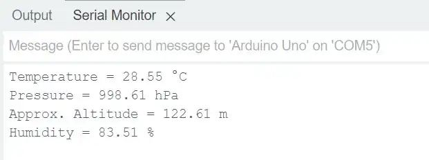
If you find an error such as “Could not find a valid BME280 sensor, check wiring, address, sensor ID!” check the troubleshooting section at the end of this article.
Here is the circuit I built with BME280 on a breadboard connected to Arduino UNO using jumpers.
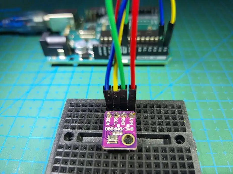
Also read: Connect Multiple Switches To 1 Pin Using ADC(Arduino How To)
Environment Sensor Arduino Code Explanation
First, we include the necessary libraries for the code to work. Wire.h and SPI.h are libraries for I2C and SPI communication protocols respectively. Adafruit_Sensor.h is a library that provides an abstract base class for sensors, and Adafruit_BME280.h is a library specifically for the BME280 sensor.
#include <Wire.h>
#include <SPI.h>
#include <Adafruit_Sensor.h>
#include <Adafruit_BME280.h>Code language: C++ (cpp)
Then we define a constant value for the sea-level pressure in hectopascals (hPa). It is used as a reference value for calculating altitude.
#define SEALEVELPRESSURE_HPA (1013.25)Code language: C++ (cpp)An object bme of the Adafruit_BME280 class is created, which represents the BME280 sensor. delayTime is an unsigned long variable used to control the delay time between sensor readings.
Adafruit_BME280 bme;
unsigned long delayTime;Code language: C++ (cpp)
The setup() function is a standard Arduino function that is executed once at the beginning. It initializes the serial communication at a baud rate of 9600. The while(!Serial); line waits until the serial connection is established. Then, it prints the “BME280 test” message to the serial monitor.
The variable status is declared to store the status of the BME280 sensor initialization. bme.begin(0x76) initializes the BME280 sensor with the I2C address 0x76.
If the initialization fails (status is zero), an error message is printed with information about the sensor’s ID. The program enters an infinite loop with a small delay if the sensor is not found.
If the initialization is successful, the code prints the “– Default Test –” message and sets the delayTime to 1000 milliseconds (1 second).
void setup() {
    Serial.begin(9600);
    while(!Serial);
    Serial.println(F("BME280 test"));
    unsigned status;
    status = bme.begin(0x76);

    if (!status) {
        Serial.println("Could not find a valid BME280 sensor, check wiring, address, sensor ID!");
        Serial.print("SensorID was: 0x"); Serial.println(bme.sensorID(),16);
        Serial.print("        ID of 0xFF probably means a bad address, a BMP 180 or BMP 085\n");
        Serial.print("   ID of 0x56-0x58 represents a BMP 280,\n");
        Serial.print("        ID of 0x60 represents a BME 280.\n");
        Serial.print("        ID of 0x61 represents a BME 680.\n");
        while (1) delay(10);
    }

    Serial.println("-- Default Test --");
    delayTime = 1000;

    Serial.println();
}
Code language: C++ (cpp)
The loop() function is another standard Arduino function that repeatedly runs after the setup(). It calls the function printValues() which will print the output to the serial monitor.
void loop() {
    printValues();
    delay(delayTime);
}Code language: JavaScript (javascript)
Monitoring Multiple BME280 Environment Sensors
We can connect multiple BME280 sensors to the same I2C lines. The sensor module has the option to change the I2C address so that two BME280 sensors can communicate with a microcontroller over the same I2C bus.
By default, the address for the module is 0x76 in hexadecimal or 1110110 in binary. This is due to a default soldered connection between two pads on the breakout board.
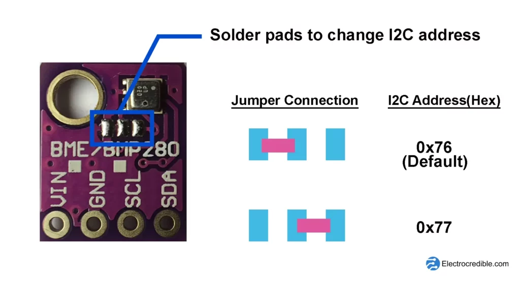
We can change the default I2C address by removing the soldered trace connecting the pads on the left and making a new connection between the two pads on the right using some solder. The new address will then be 0x77 in hexadecimal or 1110111 in binary.
Troubleshooting
A problem that users face when interfacing the BME280 sensor with Arduino is the IDE message “Could not find a valid BME280 sensor, check wiring, address, sensor ID!”. This may be due to faulty wiring, or a wrong I2C address.
Make sure that the SDA pin of the sensor connects to the SDA pin of the Arduino board. Also, verify the connection of the SDA pin. Supply the proper voltage for the sensor and development board.
The I2C address of the sensor also needs to be correct for it to communicate. You can find the I2C address by compiling and uploading the code below.
#include <Wire.h>

void setup() {
  Wire.begin();
  Serial.begin(9600);
  while (!Serial);  // Wait for serial connection
  Serial.println("\nI2C Scanner");
}

void loop() {
  byte error, address;
  int devices = 0;

  Serial.println("Scanning...");

  for (address = 1; address < 127; address++) {
    Wire.beginTransmission(address);
    error = Wire.endTransmission();

    if (error == 0) {
      Serial.print("I2C device found at address 0x");
      if (address < 16)
        Serial.print("0");
      Serial.println(address, HEX);
      devices++;
    } else if (error == 4) {
      Serial.print("Unknown error at address 0x");
      if (address < 16)
        Serial.print("0");
      Serial.println(address, HEX);
    }
  }

  if (devices == 0)
    Serial.println("No I2C devices found\n");
  else
    Serial.println("Scanning finished\n");

  delay(5000);  // Delay before next scan
}Code language: C++ (cpp)
Open the serial monitor of Arduino IDE to find the address of the BME280 sensor. Enter this address into the bme280test sketch by changing the line status = bme.begin(0x76) with the discovered address in place of “0x76”.
Wrapping Up
We hope you found this Arduino environment sensor tutorial to be helpful. If you want to use MicroPython instead of the Arduino language, we also have a tutorial to interface BME280 with RPi Pico using MicroPython.
Also read: Raspberry Pi Pico vs Arduino – Which Board To Choose?
Leave a Reply