In this tutorial, learn how to read multiple analog inputs such as pushbuttons on 1 pin in Arduino using the inbuilt Analog-to-Digital Converter(ADC).
Why would we need to connect multiple inputs to one pin? Because microcontrollers come with a limited number of I/O pins. By interfacing many switches to one pin, we can save pins for other uses. Also multiplexing pins through software leads to fewer connecting wires and less messy project development.
Overview of Input Multiplexing using ADC
The microcontroller used in the Arduino development boards has an inbuilt Analog-to-Digital Converter(ADC). For example, the Atmega328 microcontroller in Arduino UNO can convert analog voltage between 0 and 5 Volts to a 10-bit binary number.
This means that we get a decimal value between 0 and 1023 for voltages between 0 and 5 Volts. We will use this feature to read analog inputs that will differ depending on a resistor network connected to the switches.
Components Required For This Project
- Any Arduino-compatible board.
- Breadboard and connecting wires.
- Tactile pushbuttons.
- LEDs and resistors.
Method 1: How to Connect Multiple Inputs to One Arduino Pin.
In this example, we will connect 4 switches to one analog pin of Arduino. Each of these switches will control an LED.
The resistor values chosen are 1KΩ, 2.2KΩ, 4.7KΩ, and 10KΩ.
You can use any resistor you like in the kiloohm range, provided there is a significant difference between their resistances.
Connect the resistors and LEDs to an analog input pin of Arduino as shown in the image below. The 0.25 value denotes the Watt rating of the components.
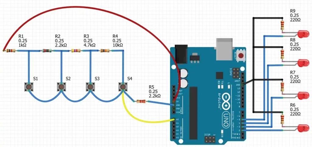
The resistors connected to the 4 switches give unique voltage values at the A0 pin of Arduino. Let us consider the case when Switch 1 (S1) is pressed and all other switches are off. Ends of the 1K (R1) and 2.2K (R5) resistors get shorted through the switch and act as a voltage divider. A basic voltage divider is shown in the image below.

The voltage seen by the A0 pin can be calculated as:
$V= 5V \times \frac{2.2K}{2.2K+1K}$
$\Rightarrow V= 3.4375\;Volts$
The corresponding digital value registered by the ADC will be 1024x( 3.4375 V ÷ 5 V)=704.
Instead of calculating this repeatedly, we shall use the following code to find the ADC value corresponding to different button presses.
Arduino Code to Get Initial ADC Readings
Copy and upload the following code to your Arduino board.
void setup() {
  Serial.begin(9600);
}

int ADC_value;
void loop(){
  ADC_value =0;
  for (int i=0; i < 6; i++){
     ADC_value += analogRead(A0);
  }
  ADC_value=  ADC_value/6;  // calculates the average value of 6 readings
  delay(200);
  Serial.println(ADC_value); //prints the ADC value in Serial Monitor
}Code language: C++ (cpp)
Now, press the 4 switches one by one, and note down the corresponding values from the Serial Monitor. We will use these values in our next program.
In my case, I got the ADC values as 700, 415, 210, and 105 corresponding to the switches S1, S2, S3, and S4 respectively. Note that the value 700 is almost close to 704, which I obtained using the formula described above.
Arduino Code to Detect Pushbutton and Toggle LEDs
The following code detects the button presses and toggles the corresponding LEDs.
# Source: Electrocredible.com, Language: Arduino
#define VAL1 700
#define VAL2 415
#define VAL3 210
#define VAL4 105


void setup() {
  //Pins for LEDs
  pinMode(2, OUTPUT);
  pinMode(3, OUTPUT);
  pinMode(4, OUTPUT);
  pinMode(5, OUTPUT);
}

int ADC_value;
unsigned long lastRead=millis(); // variable used for rejecting multiple readings within a short time
void loop(){
  ADC_value =0;
  for (int i=0; i < 40; i++){
     ADC_value += analogRead(A0);
  }
  ADC_value=  ADC_value/40;  // calculates the average value of 40 readings

  if ((ADC_value>VAL1-50)&&(ADC_value<VAL1+50)&&(millis()-lastRead>300)){
    digitalWrite(2, !digitalRead(2)); // Toggle LED
    lastRead=millis();
  }
   if ((ADC_value>VAL2-50)&&(ADC_value<VAL2+50)&&(millis()-lastRead>300)){
    digitalWrite(3, !digitalRead(3));// Toggle LED
    lastRead=millis();
  }
   if ((ADC_value>VAL3-50)&&(ADC_value<VAL3+50)&&(millis()-lastRead>300)){
    digitalWrite(4, !digitalRead(4));// Toggle LED
    lastRead=millis();
  }
  if ((ADC_value>VAL4-50)&&(ADC_value<VAL4+50)&&(millis()-lastRead>300)){
    digitalWrite(5, !digitalRead(5));// Toggle LED
    lastRead=millis();
  }
}Code language: C++ (cpp)
Code Explanation
The VAL1, VAL2, VAL3, and VAL4 variables are set to the ADC values we found from the first program.
#define VAL1 700
#define VAL2 415
#define VAL3 210
#define VAL4 105Code language: CSS (css)
Then we calculate the average value of 40 readings of the ADC. As there might be a slight deviation in readings, we use the following piece of code to detect button presses if the ADC values fall within a certain limit. Also, the time between consecutive button presses is calculated using the millis() function. Without this, we will notice multiple results in a single button press. This is similar to debouncing a push-button.
if ((ADC_value>VAL1-50)&&(ADC_value<VAL1+50)&&(millis()-lastRead>300)){
    digitalWrite(2, !digitalRead(2)); // Toggle LED
    lastRead=millis();Code language: HTML, XML (xml)
According to the code above, if the ADC values are between 650(700-50) and 750(700+50), the LED connected to Digital Pin 2 will toggle its state. You may be required to tweak this part of the code to get the desired result. Similarly, the other button press events are detected depending on the ADC reading.

Method 2: Read Multiple Push-Buttons using One Arduino ADC Pin.
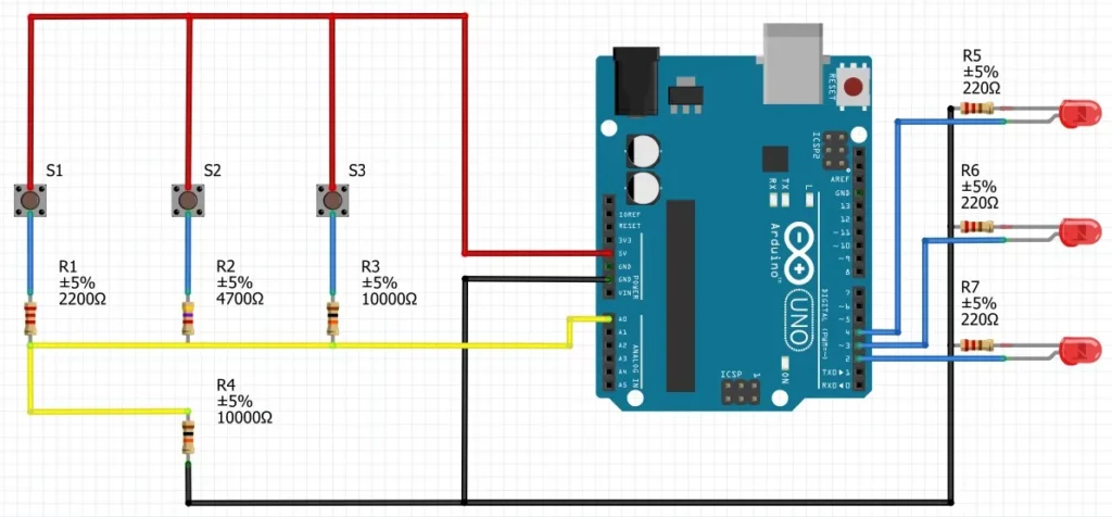
Here, we will connect 3 pushbuttons with our Arduino. Each switch will be connected to the 5V supply voltage on one end, and to the ground through resistors on the other end.
The resistors used have values of 2.2KΩ, 4.7KΩ, and 10KΩ. As long as there is a noticeable variation in resistance between the resistors, you are free to use any resistor in the kiloohm range.
Connect the resistors and LEDs to your Arduino as shown in the image below.
Use the first program in this article to know the ADC values returned by the switches.
Press the 3 switches one by one, and note down the corresponding values from the Serial Monitor. In my case, I got the ADC values as 838, 697, and 395 corresponding to resistors 2.2KΩ, 4.7KΩ, and 10KΩ respectively.
The following program can detect the pushbutton presses and toggle the respective LEDs. The code is the same as the one we saw above, except that this time we are using 3 switches.
# Source: Electrocredible.com, Language: Arduino
#define VAL1 838
#define VAL2 697
#define VAL3 395

void setup() {
  //Pins for LEDs
  pinMode(2, OUTPUT);
  pinMode(3, OUTPUT);
  pinMode(4, OUTPUT);
}

int ADC_value;
unsigned long lastRead=millis(); // variable used for rejecting multiple readings within a short time
void loop(){
  ADC_value =0;
  for (int i=0; i < 20; i++){
     ADC_value += analogRead(A0);
  }
  ADC_value=  ADC_value/20;  // calculates the average value of 20 readings

  if ((ADC_value>VAL1-50)&&(ADC_value<VAL1+50)&&(millis()-lastRead>300)){
    digitalWrite(2, !digitalRead(2)); // Toggle LED
    lastRead=millis();
  }
   if ((ADC_value>VAL2-50)&&(ADC_value<VAL2+50)&&(millis()-lastRead>300)){
    digitalWrite(3, !digitalRead(3));// Toggle LED
    lastRead=millis();
  }
   if ((ADC_value>VAL3-50)&&(ADC_value<VAL3+50)&&(millis()-lastRead>300)){
    digitalWrite(4, !digitalRead(4));// Toggle LED
    lastRead=millis();
  }
}Code language: PHP (php)
Troubleshooting
If you notice that a switch press is not registered, upload the first program in this article and view the ADC values in your Serial monitor. Changing the length of connecting wires or using different switches may change the ADC reading.
Building the circuit on a breadboard might cause errors in your ADC readings due to loose connections. It is better to solder the switches for proper results. If you have any questions or suggestions, please leave your comments below.
Also Read: Raspberry Pi Pico External Interrupts & Button Interfacing Tutorial Using MicroPython.
Leave a Reply