This article will guide you through the process of interfacing a 4×5 and 4×4 matrix membrane keypad with the Raspberry Pi Pico W development board. We will explore the essential steps involved, from connecting the keypad to the RPi Pico W pins to programming the microcontroller to effectively read the keypad’s input.
When a user enters input through the keypad, the pressed key information will be shown as an output in the console of the IDE. Thonny IDE will be used to upload MicroPython code to Raspberry Pi Pico.

Components Required
We need the following components for this guide:
- A Raspberry Pi Pico with MicroPython running on it.
- A 4×5 Matrix membrane keypad. You can also use a 4×4 keypad with slight modifications according to the instructions given later in the article.
- Breadboard and jumper cables.
Overview of 4×5 Matrix Keypad
A matrix keypad provides a small, flexible solution that makes it easy for users to enter information or make selections. They come in various sizes such as 3×4, 4×4, or 4×5. The numbers denote the columns and rows respectively. For example, a 4×5 matrix membrane keypad consists of 20 switches arranged in 4 columns and 5 rows.
Pinout of 4×5 Matrix Keypad
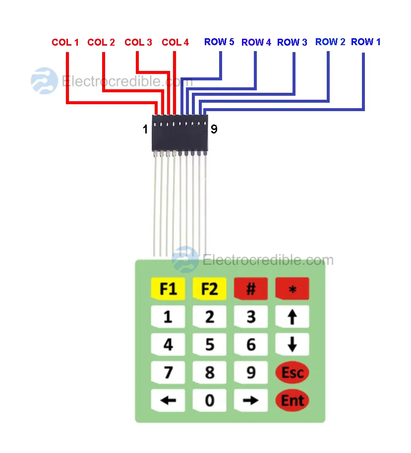
The diagram below shows how the rows and columns of a 4×5 matrix membrane keypad are connected with the female header.
How 4×5 Matrix Keypad Works
The keypad’s construction involves a thin, flexible membrane layer with conductive traces printed on it. On top of the membrane, discrete button pads correspond to each key in the matrix. When we press a button, it makes contact with the conductive traces on the membrane, creating an electrical connection.
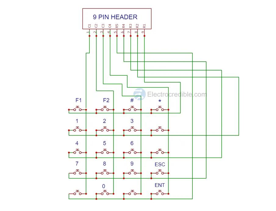
The above diagram shows how the switches are wired to the rows and columns within the membrane keypad. To detect keypress, we can give a voltage to a row (logic 1 or HIGH) and read the columns one by one to see if a voltage is present. If not, we set the next row HIGH and again scan all the columns. This procedure is repeated till a keypress is detected. For example, if we set the 1st row to logical HIGH and then we get a HIGH logic when we read column 3, we can ascertain that the “#” key was pressed.
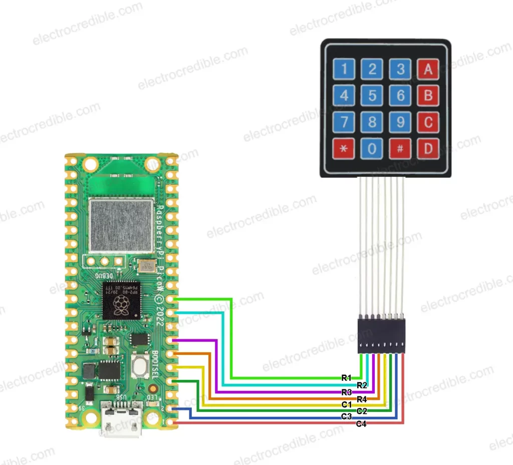
Schematic: Raspberry Pi Pico W With 4×5 Matrix Keypad
The wiring diagram below shows how the matrix keypad is connected to Raspberry Pi Pico W. You can choose any other GPIO according to convenience. The code that we will discuss below will work for this schematic.

You can refer to our Raspberry Pi Pico pinout guide while building this circuit.
Connection details:
| Raspberry Pi Pico Pin | Keypad Pin |
| GPIO 0 | COLUMN 1 |
| GPIO 1 | COLUMN 2 |
| GPIO 2 | COLUMN 3 |
| GPIO 3 | COLUMN 4 |
| GPIO 4 | ROW 5 |
| GPIO 5 | ROW 4 |
| GPIO 6 | ROW 3 |
| GPIO 7 | ROW 2 |
| GPIO 8 | ROW 1 |
GPIO 0 to GPIO 3 of Pico are connected to the column pins of the keypad while GPIO 4 to GPIO 8 are connected to the row pins. Note that if you are using any other sized keypad such as a 4×4 matrix membrane keypad, the connections of keypad wires to the microcontroller will change. The arrangement of rows and columns is different in a 4×4 matrix keypad.
Also read: Raspberry Pi Pico With PIR Motion Sensor – Send Email Alert (MicroPython Tutorial)
MicroPython Code For Raspberry Pi Pico Keypad(4×5) Interfacing
Your Raspberry Pi Pico needs to be preloaded with a MicroPython UF2 file to program it in MicroPython. You can read our getting started guide for Raspberry Pi Pico where we show all steps required to start programming RP2040 in MicroPython. Here, we will show the steps to upload code using Thonny IDE. If you are using macOS, you can read our guide to program Raspberry Pi Pico on macOS using the Thonny IDE.
- With all connections done according to the schematic, connect the Pico to your computer using a USB cable. Open Thonny IDE, and paste the following code into a new project.
from machine import Pin
import utime

keyMatrix = [
    [ "F1",  "F2",   "#",    "*"  ],
    [ "1",    "2",   "3",    "Up" ],
    [ "4",    "5",   "6",   "Down"],
    [ "7",    "8",   "9",   "Esc" ],
    ["Left",  "0", "Right", "Ent" ]
]
colPins = [0,1,2,3]
rowPins = [8,7,6,5,4]

row = []
column = []

for item in rowPins:
    row.append(machine.Pin(item,machine.Pin.OUT))
for item in colPins:
    column.append(machine.Pin(item,machine.Pin.IN,machine.Pin.PULL_DOWN))
key = '0'
def scanKeypad():
    global key
    for rowKey in range(5):
        row[rowKey].value(1)
        for colKey in range(4):
            if column[colKey].value() == 1:
                key = keyMatrix[rowKey][colKey]
                row[rowKey].value(0)
                return(key)
        row[rowKey].value(0)
def printKey():
    key=scanKeypad()
    if key is not None:
        print("Key pressed is:{}".format(key))
    utime.sleep(0.2)

while True: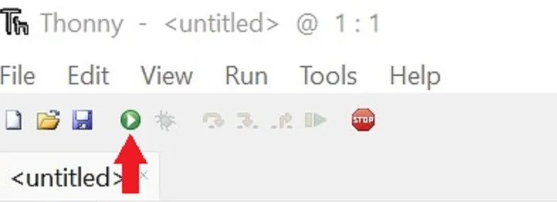
printKey()Code language: Python (python)- Run the code by clicking the Run icon or by pressing the F5 key.
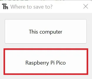
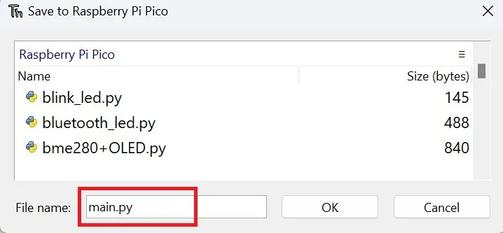
- Save the script to your Raspberry Pi Pico.
- Save the script as main.py or with any other name with a “.py” filename extension.
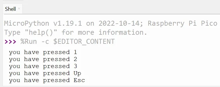
Now, press any key on the matrix keypad. The image below shows the output in the shell of Thonny IDE when I pressed the “1”, “2” and “3”, “Up” and “Esc” keys consecutively.
MicroPython Code Explanation
First, we import two necessary MicroPython modules. The Pin class is used for controlling the pins of the microcontroller, and utime is used for setting delays in code.
from machine import Pin
import utimeCode language: Python (python)
Next, we define a 2-dimensional list called keyMatrix that represents the keypad layout. It contains the labels for each key in the 4×5 membrane keypad.
keyMatrix = [
    [ "F1",  "F2",   "#",    "*"  ],
    [ "1",    "2",   "3",    "Up" ],
    [ "4",    "5",   "6",   "Down"],
    [ "7",    "8",   "9",   "Esc" ],
    ["Left",  "0", "Right", "Ent" ]
]Code language: Python (python)
Then we define two lists, colPins and rowPins, which represent the column and row pins of the keypad. These lists specify the GPIO pins on the Raspberry Pi Pico that are connected to the keypad through wires.
colPins = [0,1,2,3]
rowPins = [8,7,6,5,4]Code language: Python (python)
Two empty lists, row and column, will be used to store instances of Pin for the rows and columns of the keypad. We will use this list to set the pins as input and output with the help of a for loop.
row = []
column = []Code language: Python (python)
A for loop iterates over each item in rowPins list and creates a Pin instance for each item, setting the pin mode to output. The resulting Pin objects are then appended to the row list.
for item in rowPins:
    row.append(machine.Pin(item,machine.Pin.OUT))Code language: Python (python)
Another loop does a similar operation as the previous one but for the column pins. It creates Pin instances for each item, sets the pin mode to input, and enables the internal pull-down resistor on each pin. The resulting Pin objects are appended to the column list.
for item in colPins:
    column.append(machine.Pin(item,machine.Pin.IN,machine.Pin.PULL_DOWN))Code language: Python (python)
The key variable is initialized with a default value of ‘0’.
key = '0'Code language: Python (python)The function scanKeypad() is defined to scan the keypad for key presses. It iterates over the rows and columns of the keypad, setting the value of each row to 1 and checking the value of each column. If a key is pressed (column value is 1), it updates the key variable with the corresponding key from keyMatrix and returns the key value. After each row iteration, it sets the row value back to 0.
def scanKeypad():
    global key
    for rowKey in range(5):
        row[rowKey].value(1)
        for colKey in range(4):
            if column[colKey].value() == 1:
                key = keyMatrix[rowKey][colKey]
                row[rowKey].value(0)
                return(key)
        row[rowKey].value(0)Code language: Python (python)
The printKey() function scans the keypad and monitors if any key is pressed. When a keypress is detected, its value is printed on the shell of the IDE. A delay of 200ms in the function acts as a debounce. Without this, a single key press might register multiple inputs.
def printKey():
    key=scanKeypad()
    if key is not None:
        print("Key pressed is:{}".format(key))
    utime.sleep(0.2)Code language: Python (python)
An infinite while loop is started, where the printKey() function is called to check for button presses.
while True:
    printKey()Code language: Python (python)
Also Read: Arduino vs MicroPython vs CircuitPython: Which One Will You Choose?
Schematic & Code For 4×4 Keypad With Raspberry Pi Pico
If you are using a 4×4 keypad with Pico, the schematic is given below.
The MicroPython code for this schematic has some slight variations from the code we discussed earlier. The keyMatrix list needs to be changed to define the changed key layout. The colPins and rowPins also needs to be changed as follows.
colPins = [3,2,1,0]
rowPins = [7,6,5,4]Code language: Python (python)
The scanKeypad function will be as shown below.
def scanKeypad():
    global key
    for rowKey in range(4):
        row[rowKey].value(1)
        for colKey in range(4):
            if column[colKey].value() == 1:
                key = keyMatrix[rowKey][colKey]
                row[rowKey].value(0)
                return(key)
        row[rowKey].value(0)Code language: Python (python)
Wrapping Up
In this guide, we learned how to connect a 4×5 matrix keypad with Raspberry Pi Pico W and how to upload a MicroPython script so that we can read key presses. With slight modifications, we also learned how to interface a 4×4 matrix keypad with Pico. For further experimentation, you can also interface an LCD with Raspberry Pi Pico to show the output of the keypad. You can use this guide for projects such as:
- A simple calculator.
- Password-based home security system.
Also read:
Leave a Reply