Flow sensors are widely used to measure the volume or flow rate of a liquid flowing through a pipe. The sensor can be placed in the path of water flow. Its waterproof design ensures that no liquid can come in contact with the electronic components inside the sensor. You can read this sensor by connecting with various microcontrollers like Arduino, STM32, Raspberry Pi Pico, etc.
YF-S201 Flow Sensor Pinout
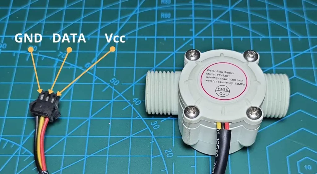
The diagram above shows the pinout of the YF-S201 flow sensor. Most of the commercially available YF-S201 sensors have 3 wires for interfacing. The details of the pins are given in the table below.
| YF-S201 Wire Color | Description |
| Red | VIN(5V-24V) |
| Black | Ground |
| Yellow | Data |
How it Works
Flow sensor works on the principle of the Hall Effect. According to Hall Effect, when a current-carrying conductor is placed in a magnetic field perpendicular to the current direction, an electric field is induced in the conductor perpendicular to both the electric current and the magnetic field.

In the image above, the voltage VH denotes the Hall Voltage. It depends on the strength of the magnetic field, current, charge carrier density, cross-sectional area of the conductor, and charge of an electron. The direction of the Hall current is perpendicular to both the applied electric field and the magnetic field.
Let us look at the internal diagram of the YF-S201 flow sensor to understand how the flow sensor works.

Inside, there is a freely rotating wheel placed inside an outer plastic case. The case is made waterproof using rubber O-rings and keeps the electronic components isolated. There is a permanent magnet attached near the axle of the wheel. When liquid flows through the sensor, the magnet also revolves with the wheel. This produces a spinning magnetic field that causes the Hall Effect Sensor to experience a voltage.
A microprocessor or microcontroller can read the pulses generated by the Hall Effect Sensor, and estimate the flow rate of liquid through the sensor. This can be easily done using interrupts in microcontrollers.

View of the Hall Effect Sensor up close within the YF-S201 flow sensor. Rubber seals in the enclosure effectively prevent water damage to this circuit.
YF-S201 Flow Sensor Specifications
- Supply Voltage: 5 to 24V DC
- Flow Rate: 1 to 30 Liters / Minute
- Sensor Output Voltage: 5V TTL
- Accuracy: ±10%
- Maximum liquid pressure: 1.75 MPa
Applications of Flow Sensor
- To measure the flow of liquid in Hydroponic systems or Drip-irrigation systems.
- HVAC systems.
- Chemical factories
- Sewage management.
- Pump automation.
Interfacing YF-S201
Interfacing with 5V compatible development boards such as Arduino UNO is easily accomplished with a few lines of code. To use it with 3.3V operated microcontrollers, we might require a logic level shifter.
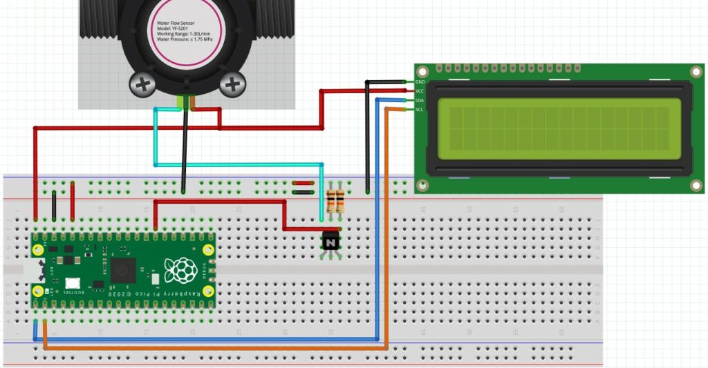
Read our article How to interface YF-S201 flow sensor with Raspberry Pi Pico to learn how we can easily use this sensor.
Leave a Reply