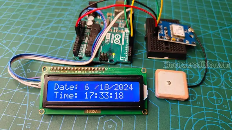
Get the power of an atomic clock by using a GPS receiver (NEO-6M module) and an Arduino. This article will guide you to build a DIY clock without using an RTC (Real Time Clock). RTCs are used wherever precise timekeeping is necessary. RTCs use battery backup and memory to keep track of time.
Although a GPS receiver is often used to know the position or location, it can be used for time-keeping. GPS receivers are an alternative to these RTCs that can work anywhere globally. Such a time-keeping device can be useful in remotely installed long-term applications.
How GPS Time Works

GPS or global positioning system uses a constellation of satellites. Each of these satellites has onboard atomic clocks which are extremely accurate and keep precise time to within a few nanoseconds.
Each satellite continuously transmits a signal that includes the current time according to its onboard clock and the satellite’s position at the time of signal transmission. When a GPS receiver gets the signal, it notes the exact time of arrival of the signal.
Given that the signal travels at the speed of light, the time taken for the signal to reach the receiver can be calculated if the receiver’s clock were perfectly synchronized with the satellite’s clock. GPS receivers have their own clock which are initially out of sync.
To determine its exact position, the receiver needs signals from at least four satellites. By comparing the time stamps from at least four different satellites, the receiver can solve a set of equations to find its own position and correct its own clock.
Components Required
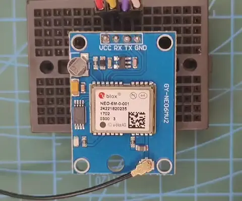
- NEO-6M GPS module.
- Any Arduino development board.
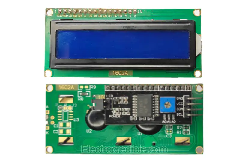
- 16×2 I2C LCD Module.
The U-blox NEO-6M GPS chip is commonly available in a breakout board module called the GY-NEO6MV2 or the GY-GPS6MV2. It can easily interface with a microcontroller using serial communication.

The LCD module used in this project contains an I2C port expander IC which helps us to easily interface it with just 4 wires.
Also read: Interface Arduino with SSD1306 OLED Display Using I2C
Interfacing GPS Module with Arduino
It is easy to interface with the NEO-6M GPS module using a readymade Arduino library and just 4 wires for data exchange and power.
We have already written an article that describes how to wire the GPS module with Arduino, get raw GPS data, and use the TinyGPS++ library to easily obtain meaningful data.
Read our in-depth guide here:
DIY GPS Clock using Arduino, LCD, and NEO-6M Module
In this project, we shall only use the date and time information obtained from the GPS receiver and display it on an LCD.
Wiring
Connect the 16×2 LCD module, Arduino UNO, and NEO-6M GPS module as shown below:
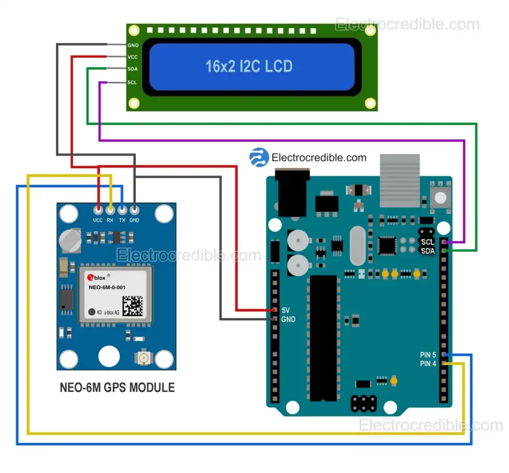
We use Arduino’s software serial library to interface with the GY-NEO6MV2 GPS module using digital pins. This allows us to use the hardware serial pins in Arduino to communicate with the Serial Monitor in Arduino IDE if required. Digital pins 4 and 5 in Arduino UNO are used as TX (Transmit) and RX (Receive) pins respectively.
Note: The TX pin in Arduino is connected to the RX pin of the GPS module and vice versa.
The 16×2 I2C LCD module connects to the default I2C pins on Arduino UNO.
Arduino Libraries
In Arduino IDE, select the development board you are using and also select the correct serial port for your board.
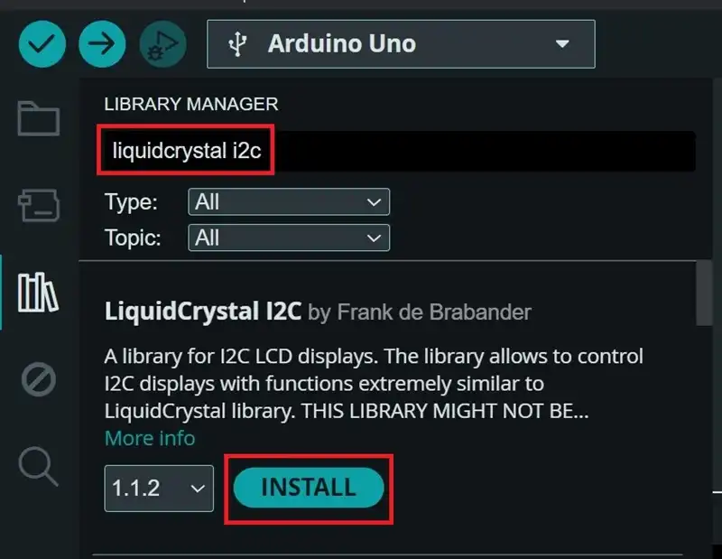
To interface the LCD, we require the LiquidCrystal I2C library by Frank de Brabander. You can install it in Arduino IDE by navigating to Tools>Manager Libraries. Search for “LiquidCrystal I2C” and install it.
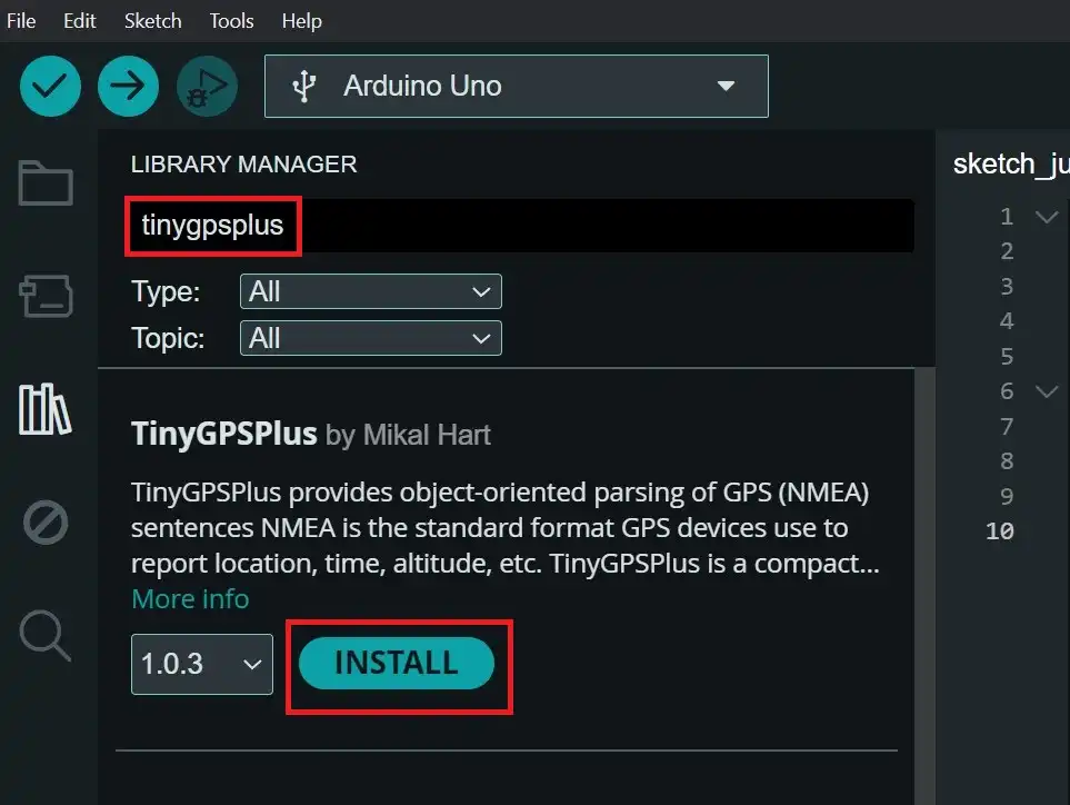
The NEO-6M GPS module requires the TinyGPS++ library which can also be installed from the Library Manager in Arduino IDE by searching for “tinygpsplus”.
Arduino Code
After wiring the circuit as described and after the necessary libraries are installed, upload the following Arduino code to display the date and time on the LCD.
#include <TinyGPS++.h>
#include <SoftwareSerial.h>
#include <Wire.h>
#include <LiquidCrystal_I2C.h>

LiquidCrystal_I2C lcd(0x27,16,2);  // set the LCD address to 0x27 for a 16 chars and 2 line display

// Define pins for SoftwareSerial
const int RX_Pin = 5;
const int TX_Pin = 4;

const int GPS_Baud_Rate = 9600;

// Instantiate TinyGPS++ object
TinyGPSPlus gpsModule;

// Create software serial port named "gpsSerialPort"
SoftwareSerial gpsSerialPort(RX_Pin, TX_Pin);

void setup()
{
  // Initialize the hardware serial communication at 9600 baud
  Serial.begin(9600);

  // Initialize the software serial port at the GPS module's default baud rate
  gpsSerialPort.begin(GPS_Baud_Rate);

  lcd.init();                      // initialize the lcd
  lcd.backlight();                 //turn the backlight ON
}

void loop()
{
  // Process incoming GPS data
  while (gpsSerialPort.available() > 0)
    if (gpsModule.encode(gpsSerialPort.read()))
    {
      display_on_LCD();
    }

  // Check if no GPS data has been received for 5 seconds
  if (millis() > 5000 && gpsModule.charsProcessed() < 10)
  {
    Serial.println("Error: GPS module not detected");
    while (true);
  }
}

void display_on_LCD()
{
  lcd.clear();
  if (gpsModule.date.isValid())
  {
      lcd.setCursor(0,0);
      lcd.print("Date:");

      lcd.setCursor(6,0);
      lcd.print(gpsModule.date.month());

      lcd.setCursor(8,0);
      lcd.print("/");

      lcd.setCursor(9,0);
      lcd.print(gpsModule.date.day());

      lcd.setCursor(11,0);
      lcd.print("/");

      lcd.setCursor(12,0);
      lcd.print(gpsModule.date.year());

      lcd.setCursor(0,1);
      lcd.print("Time:");

      lcd.setCursor(6,1);
      lcd.print(gpsModule.time.hour());

      lcd.setCursor(8,1);
      lcd.print(":");

      lcd.setCursor(9,1);
      lcd.print(gpsModule.time.minute());

      lcd.setCursor(11,1);
      lcd.print(":");

      lcd.setCursor(12,1);
      lcd.print(gpsModule.time.second());

  }

}Code language: PHP (php)
Demonstration
The GPS module needs some time for a position fix during a cold start. When the module is first powered on after a long time, it is called a cold start. After the initial power-up, subsequent power-ups (hot start) will require less time to get a fix. The onboard rechargeable battery on the NEO-6M module helps to get the Time-To-First-Fix (TTFF) of under 1 second during hot start.
Wait for some time for the correct time to be displayed on the LCD. The position fix is quicker under a clear view of the sky but may take a few minutes indoors. When a position fix is found, the onboard LED on the NEO-6M module will start blinking.
The time displayed on the LCD is GPS time which is similar to UTC but a little ahead of it (+18sec at the time of publishing this article). Coordinated Universal Time (UTC) is the primary time standard globally used to regulate clocks and time.
“The time “0” which first GPS timing started is midnight on January 6th, 1980 (UTC): in that year, the GPS time coincided exactly with UTC, as a result of corrective measures to UTC, today it differs by 18 (it was 17 until December 31st 2016 and 16 seconds until June 30th 2015), seconds compared to GPS time, which as written above, is not subject to any astronomical adjustment.”
–ipses
You can learn more about the relationship between UTC and GPS time by referring to this discussion on GPS time.
To display the local time in your DIY GPS clock, you need to make a few changes in the Arduino code.
For example, if you stay in the Eastern Time Zone, the time is (UTC−04:00) when observing daylight saving time i.e. it is four hours behind UTC. In this case, you need to modify the Arduino code as follows:
lcd.print(gpsModule.time.hour()-4);Code language: CSS (css)Troubleshooting
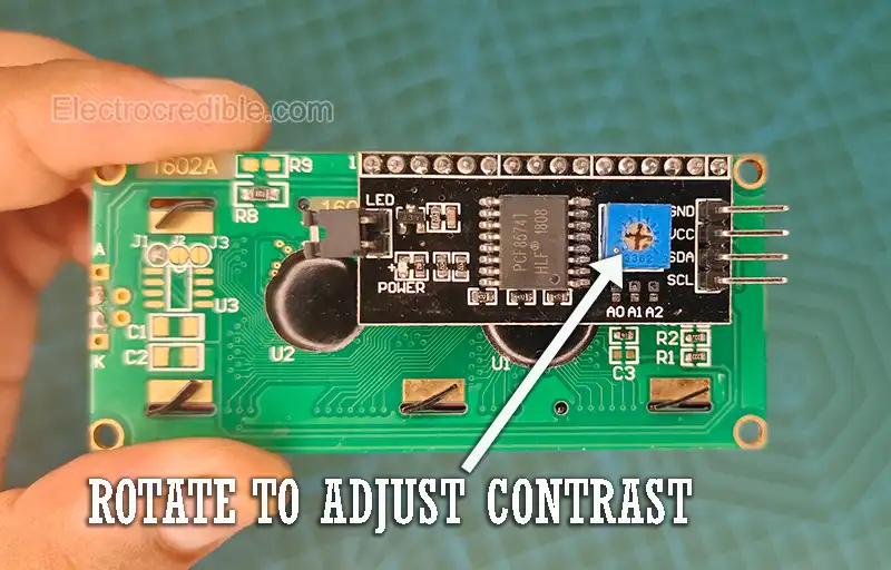
If the characters are not visible in the LCD, you might need to adjust the contrast-adjusting potentiometer on the back of the I2C LCD module.
Another problem that may arise is the I2C address of the LCD module. The address is 0x27 in most cases. You can find the I2C address of the LCD by wiring the LCD with Arduino and then uploading the following Arduino code:
#include <Wire.h>

// Set I2C bus to use: Wire, Wire1, etc.
#define WIRE Wire

void setup() {
  WIRE.begin();
  Serial.begin(9600);
  while (!Serial)
     delay(10);
  Serial.println("\nI2C Scanner");
}

void loop() {
  byte error, address;
  int nDevices;

  Serial.println("Scanning...");

  nDevices = 0;
  for(address = 1; address < 127; address++ )
  {
    WIRE.beginTransmission(address);
    error = WIRE.endTransmission();

    if (error == 0)
    {
      Serial.print("I2C device found at address 0x");
      if (address<16)
        Serial.print("0");
      Serial.print(address,HEX);
      Serial.println("  !");
      nDevices++;
    }
    else if (error==4)
    {
      Serial.print("Unknown error at address 0x");
      if (address<16)
        Serial.print("0");
      Serial.println(address,HEX);
    }
  }
  if (nDevices == 0)
    Serial.println("No I2C devices found\n");
  else
    Serial.println("done\n");
  delay(5000);           // wait 5 seconds before next scan
}Code language: PHP (php)
The address will be shown on the Serial Monitor of Arduino IDE.
Change the following line of code to change the I2C address. Replace 0x27 with the hex address of your LCD.
LiquidCrystal_I2C lcd(0x27,16,2);If the LED in the NEO-6M GPS module does not start blinking after being powered for a long time, take the circuit outside with a clear view of the sky.
Conclusion
In this tutorial, we discussed how to make a simple GPS clock using Arduino that brings the power of atomic clocks using just a few components. Also, read the following related articles on time-keeping:
Leave a Reply