This tutorial will help you to interface the NEO-6M GPS module with Arduino development boards. GPS stands for Global Positioning System which helps us to know our location anywhere on earth with the help of satellites. In addition to latitude, longitude, altitude, and speed, a GPS sensor can also let us know the local time. So, let us learn how to interface with this useful sensor that can be used in many projects.
Here, you will learn:
- How to wire the NEO-6M with an Arduino board.
- Get Raw data from the GPS sensor using serial communication with an Arduino board.
- Extract meaningful data from the Raw data such as position, time, or altitude.
- Use an Arduino library to easily read the GPS sensor.
NEO-6M GPS Module Overview
The U-blox NEO-6M GPS module is commonly available in a breakout board module called GY-NEO6MV2 or GY-GPS6MV2. This module has an onboard 5V to 3.3V voltage regulator so interfacing with microcontrollers is easy without requiring a logic level shifter. The GPS module is bundled with an antenna that snaps onto the board through a U.FL connector.
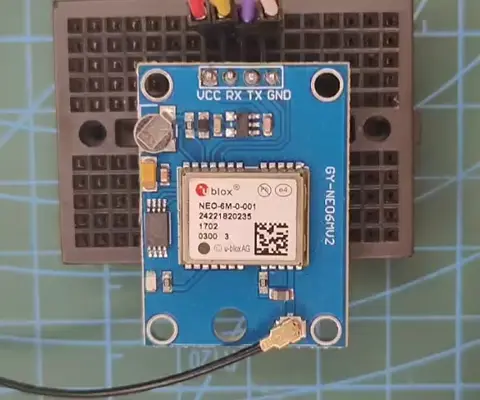
The pinout consists of 4 through-hole solder pads used for serial communication with a microcontroller. Solder four pin headers to the holes for easily connecting it with a breadboard. The pinout and onboard components of the NEO-6M GPS module are shown below.

An LED onboard the GPS module informs the status of the GPS connection. The EEPROM IC together with a rechargeable battery helps in getting the GPS position fix quickly.
Specifications of NEO-6M GPS Module:
- Altitude measurement up to 50000 meters.
- Velocity measurement up to 500m/s with an accuracy of 0.1m/s.
- GPS horizontal position accuracy of 2.5 m.
- Hot-start Time-To-First-Fix (TTFF) of under 1 second.
- Tracking and navigation sensitivity of -161 dBm.
Arduino GPS Module Wiring
The NEO-6M GPS module can communicate with a microcontroller via serial data. We use Arduino’s software serial library to interface with the GPS module using digital pins. The hardware serial pins in Arduino UNO are not used as they are required to display the data sent from the GPS module on the Serial Monitor of Arduino IDE.
Connect the NEO-6M GPS module with Arduino UNO as shown in the circuit diagram below:
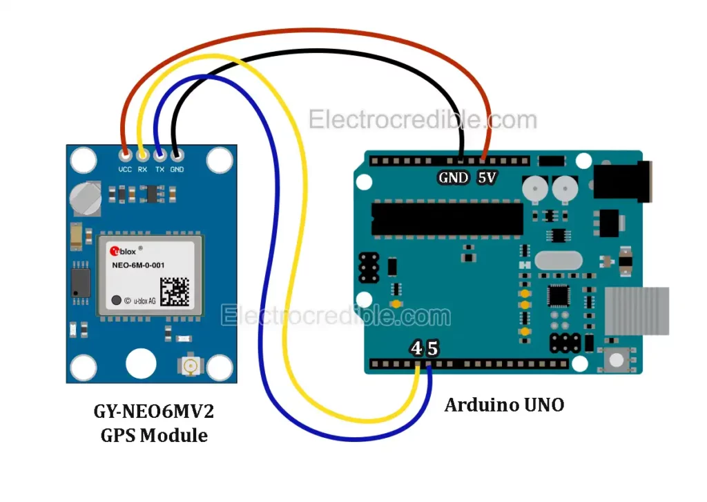
You can use any digital pins as virtual serial pins in Arduino. Here we use the pins 4 and 5 in Arduino UNO as TX(Transmit) and RX(Receive) pins respectively.
Steps for wiring:
- Connect digital pin 4 of Arduino UNO to the RX pin of the NEO-6M GPS module.
- Connect digital pin 5 to the TX pin of the NEO-6M GPS module.
- Connect the 5V output pin of Arduino UNO to the VCC pin of the NEO-6M module.
- Connect a GND pin of Arduino to the GND pin of the NEO-6M module.
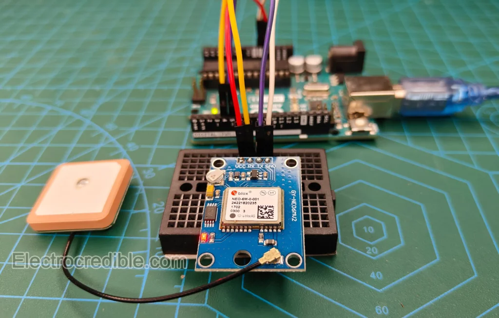
Here is how I built the circuit using jumper wires and a breadboard:
Get Raw Data on Arduino from NEO-6M GPS Module
Let us write a simple Arduino program to get data from the NEO-6M GPS module and display it on the serial monitor of Arduino IDE. The raw data is in a standard format through which we need to extract meaningful information.
Connect your Arduino board to your PC. In Arduino IDE, select your board (e.g.Arduino UNO) by going to Tools>Board. Select the correct COM port from Tools>Port.
Arduino Code for Raw Data
Upload the following Arduino code to retrieve raw GPS data from the NEO-6M module.
#include <SoftwareSerial.h>

//Pins for software serial
#define tx_pin 4
#define rx_pin 5

// Create an instance of the SoftwareSerial class
SoftwareSerial gpsPort(rx_pin, tx_pin);

void setup()
{
  Serial.begin(9600);  // Set 9600 as hardware serial baud rate
  gpsPort.begin(9600); //Set 9600 as software serial baud rate
}

void loop()
{
  // Displays raw GPS data when available
  while (gpsPort.available() > 0)
    Serial.write(gpsPort.read());
    delay(1000);
}Code language: PHP (php)
Analyzing the GPS Data
After you upload the code, open the Serial Monitor in Arduino IDE (Tools>Serial Monitor) to view the data sent from the GPS module. Set the baud rate in the Serial Monitor to 9600.
The data in the Serial monitor may be gibberish for the first few minutes. The GPS module needs some time for a position fix during a cold start. Here is how the output might look with noisy data:

When the module is first powered on after a long time, it is called a cold start. After the initial power-up, subsequent power-ups (hot start) will require less time to get a fix. The onboard rechargeable battery on the NEO-6M module helps to get the Time-To-First-Fix (TTFF) of under 1 second during hot start.
Wait for some time till you get meaningful data. When a position fix is found, the onboard LED on the NEO-6M module will start blinking.
After a few minutes, you must see the output as shown below.

The lines of data are in NMEA format. NMEA stands for National Marine Electronics Association. It is a standard data format used in GPS. Each comma-separated line that starts with a $ sign gives us different information.
For example, the line starting with $GPGGA is a basic GPS NMEA message that contains the following information separated by commas:
- Current time in UTC.
- Latitude.
- Longitude.
- GPS status(1=GPS fix).
- Number of satellites being tracked.
- Horizontal dilution of position.
- Altitude in Meters above mean sea level.
- Height of geoid.
- Time in seconds since the last DGPS update.
- DGPS station ID number.
- The checksum data (always begins with *).
You can learn more about NMEA on its Wikipedia page.
Instead of working with this raw GPS data and parsing it, it is easier to use a readymade library to obtain location and other information.
Using TinyGPS++ Library with NEO-6M GPS Module
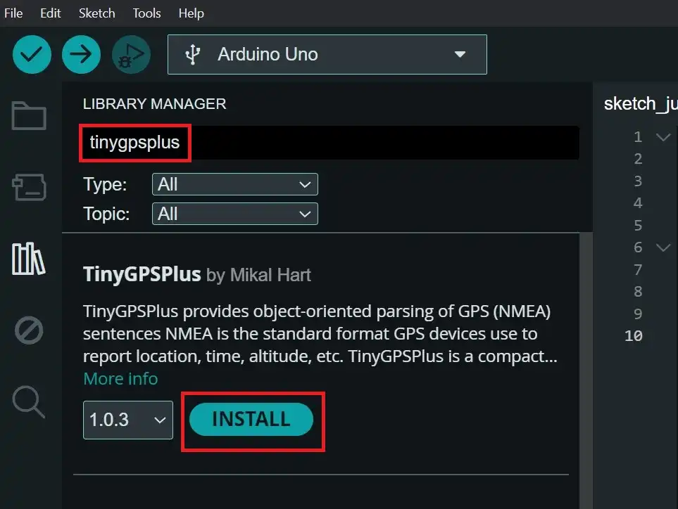
The TinyGPSPlus is an NMEA message-parsing library compatible with Arduino code. To install it on Arduino IDE, go to Sketch>Include Library>Manage Libraries. Search “tinygpsplus” and install the latest version.
NEO-6M GPS Arduino Code
With the TinyGPS++ library installed, upload the following Arduino program to get the location, date, and time using the GPS module.
#include <TinyGPS++.h>
#include <SoftwareSerial.h>

// Define pins for SoftwareSerial
const int RX_Pin = 5;
const int TX_Pin = 4;

const int GPS_Baud_Rate = 9600;

// Instantiate TinyGPS++ object
TinyGPSPlus gpsModule;

// Create software serial port named "gpsSerialPort"
SoftwareSerial gpsSerialPort(RX_Pin, TX_Pin);

void setup()
{
  // Initialize the hardware serial communication at 9600 baud
  Serial.begin(9600);

  // Initialize the software serial port at the GPS module's default baud rate
  gpsSerialPort.begin(GPS_Baud_Rate);
}

void loop()
{
  // Process incoming GPS data
  while (gpsSerialPort.available() > 0)
    if (gpsModule.encode(gpsSerialPort.read()))
      displayGPSData();

  // Check if no GPS data has been received for 5 seconds
  if (millis() > 5000 && gpsModule.charsProcessed() < 10)
  {
    Serial.println("Error: GPS module not detected");
    while (true);
  }
}

void displayGPSData()
{
  if (gpsModule.location.isValid())
  {
    Serial.print("Latitude: ");
    Serial.println(gpsModule.location.lat(), 6); //print latitude
    Serial.print("Longitude: ");
    Serial.println(gpsModule.location.lng(), 6); //print longitude
    Serial.print("Altitude: ");
    Serial.println(gpsModule.altitude.meters()); //print altitude
  }
  else
  {
    Serial.println("Location: Unavailable");
  }

  Serial.print("Current Date: ");
  if (gpsModule.date.isValid())
  {
    Serial.print(gpsModule.date.month());
    Serial.print("/");
    Serial.print(gpsModule.date.day());
    Serial.print("/");
    Serial.println(gpsModule.date.year());
  }
  else
  {
    Serial.println("Date Unavailable");
  }

  Serial.print("Current Time: ");
  if (gpsModule.time.isValid())
  {
    if (gpsModule.time.hour() < 10) Serial.print("0");
    Serial.print(gpsModule.time.hour());
    Serial.print(":");
    if (gpsModule.time.minute() < 10) Serial.print("0");
    Serial.print(gpsModule.time.minute());
    Serial.print(":");
    if (gpsModule.time.second() < 10) Serial.print("0");
    Serial.print(gpsModule.time.second());
    Serial.print(".");
    if (gpsModule.time.centisecond() < 10) Serial.print("0");
    Serial.println(gpsModule.time.centisecond());
  }
  else
  {
    Serial.println("Unavailable");
  }

  Serial.println();
  delay(1000);  // Delay before the next data display
}Code language: PHP (php)
If you want to use other digital pins for software serial, change the following lines:
const int RX_Pin = 5;
const int TX_Pin = 4;Code language: JavaScript (javascript)
Output
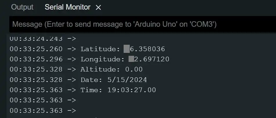
Open the Serial Monitor of Arduino IDE to view the GPS data. The baud rate of the Serial Monitor should be set at 9600.
Do not worry if “Location: Uavailable” shows up. You may need to wait for some time for the GPS fix. It took around 5 minutes to get the first position fix when I powered up the module for the first time.
Here is the output in the Serial Monitor of Arduino IDE after the GPS got a position fix:
If it takes a long time to get a fix, take the circuit outdoors under a clear view of the sky. Once you get a position fix, the sensor should work indoors too.
To get additional information such as speed, HDOP, or to measure distance, you can follow this example in Github.
Conclusion
This tutorial explained how to interface the GY-NEO6MV2 / GY-GPS6MV2 GPS breakout board with Arduino. Now that you are familiar with interfacing GPS module, you can expand your knowledge by making this GPS clock using Arduino.
Leave a Reply